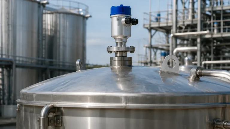
K Tek Radar Level Transmitter
K Tek Radar Level Transmitter: A Technical Guide to Industrial Radar Level Measurement
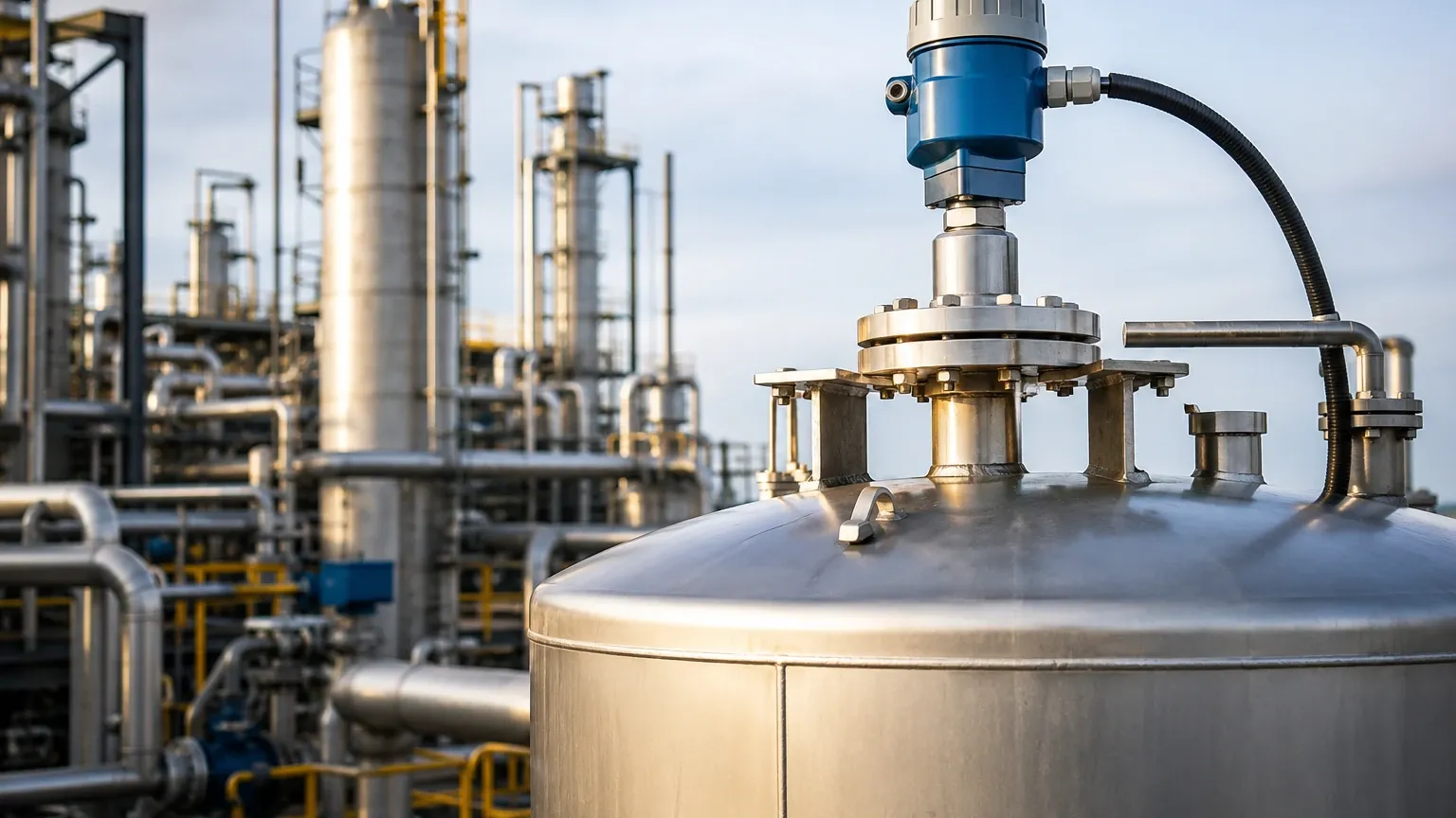
In the landscape of industrial process control, the accuracy of level measurement directly impacts safety, efficiency, and profitability. Among the various technologies available, radar-based systems have emerged as the gold standard for challenging environments. The k tek radar level transmitter—a product line now integrated into the ABB instrumentation portfolio—represents a significant milestone in the evolution of Guided Wave Radar (GWR) and non-contact microwave technology.
This guide provides a comprehensive engineering reference for understanding the principles, selection criteria, and installation requirements for radar level measurement, specifically focusing on the capabilities associated with K-Tek's legacy of high-performance transmitters and modern Radar Level Meters.
1. Measurement Principles of Radar Technology
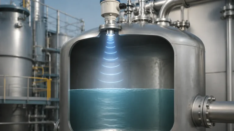
Radar level transmitters operate on the principle of Time Domain Reflectometry (TDR) or Frequency Modulated Continuous Wave (FMCW). Both methods rely on the transmission of electromagnetic pulses or waves toward a target medium and the subsequent detection of the reflected signal.
Time Domain Reflectometry (Guided Wave Radar)
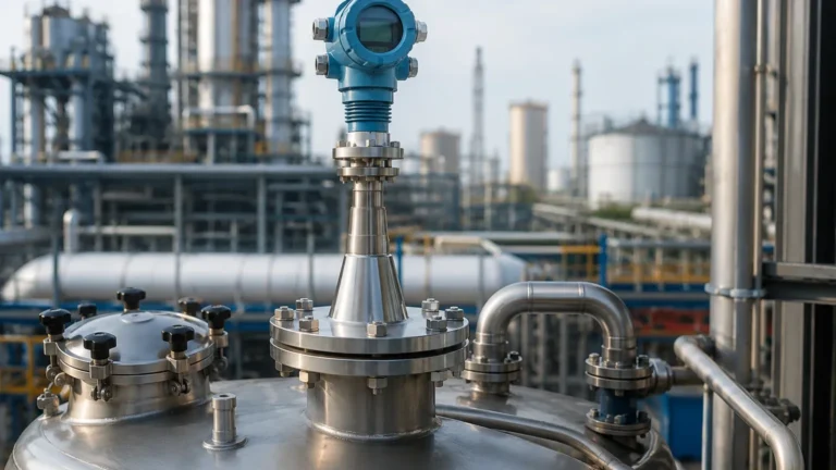
Guided Wave Radar, the technology that popularized the k tek radar level transmitter series (such as the MT5000), utilizes a physical probe to guide the microwave pulse. The pulse travels down the probe at the speed of light. When it encounters a change in the dielectric constant ($ε_r$)—typically the transition from air to a liquid or solid—a portion of the energy is reflected back to the transmitter.
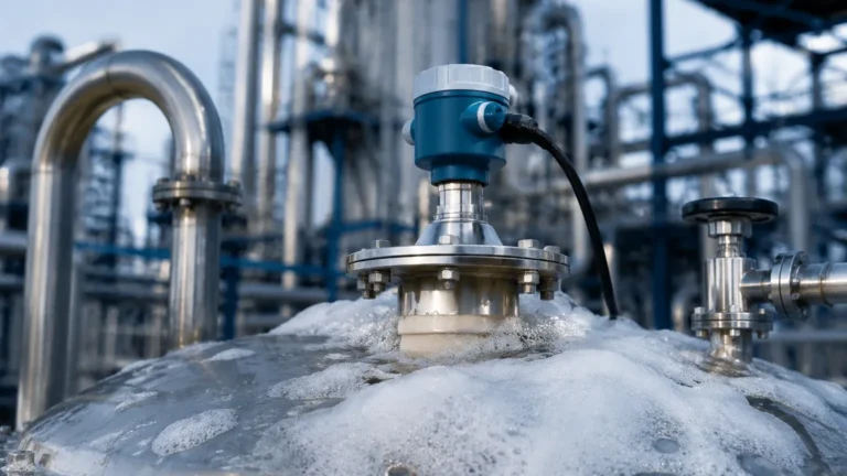
By measuring the time of flight between the transmission and the receipt of the echo, the device calculates the distance to the surface. Because the signal is confined to a probe, GWR is less affected by internal tank obstructions, foam, or turbulence compared to non-contact methods.
Non-Contact Radar (Free Space)
Non-contact radar transmitters emit microwave signals through the air via an antenna. These signals bounce off the surface of the medium and return to the receiver. Modern high-frequency radar (typically 26 GHz or 80 GHz) allows for narrower beam angles, which minimizes interference from tank walls and internal structures. This technology is ideal for corrosive media or applications where the sensor must not touch the process material.
2. Technical Comparison: GWR vs. Non-Contact Radar
Choosing between a guided wave k tek radar level transmitter and a non-contact radar level meter requires an understanding of the application's physical constraints.
| Feature | Guided Wave Radar (GWR) | Non-Contact Radar |
| :— | :— | :— |
| Medium Contact | Contacting (Probe) | Non-contacting |
| Dielectric Constant | Can measure as low as 1.4 | Generally requires > 1.9 |
| Foam Handling | Excellent (penetrates foam) | Variable (can be absorbed) |
| Turbulence | High resistance | Moderate resistance |
| Internal Obstructions | Ignores obstacles near probe | Requires clear line of sight |
| Max Range | Up to 60 m (200 ft) | Up to 100 m (328 ft) |
| Maintenance | Probe cleaning may be required | Minimal maintenance |
3. Key Selection Criteria for Industrial Applications
When specifying a radar level transmitter, engineers must evaluate the following factual boundaries to ensure long-term reliability.
Dielectric Constant ($ε_r$)
The dielectric constant of the process material is the most critical factor in signal reflection. Materials with high dielectrics (e.g., water, $ε_r ≈ 80$) reflect signals strongly. Hydrocarbons and oils have low dielectrics ($ε_r ≈ 1.8$ to $4.0$), which reflect less energy. For extremely low dielectric fluids, a guided wave k tek radar level transmitter with a coaxial probe is often recommended to concentrate the signal energy.
Process Temperature and Pressure
Radar electronics are sensitive to heat. While the antenna or probe can withstand high temperatures (up to 450°C or 842°F in specialized models), the transmitter housing must be kept within its operating range. Pressure ratings must also be verified, especially in high-pressure boiler or reactor applications where glass-to-metal seals are required for safety.
Interface Measurement
One of the unique strengths of GWR technology is the ability to measure the interface between two liquids, such as oil over water. The radar pulse passes through the upper, low-dielectric layer and reflects off the lower, high-dielectric layer. This allows for simultaneous measurement of the total level and the interface level with a single instrument.
4. Installation Best Practices and Geometric Constraints
Proper installation is paramount to preventing false echoes and ensuring signal integrity.
Nozzle Design
For non-contact radar, the antenna should ideally extend beyond the nozzle into the tank. If the antenna is recessed, signal ringing within the nozzle can create a "dead zone" at the top of the tank. For a k tek radar level transmitter using GWR, the nozzle diameter should be large enough to prevent the probe from touching the nozzle wall, which would cause a false high-level reading.
Beam Angle and Obstructions
Non-contact radar emits a cone-shaped signal. Engineers must calculate the beam diameter at the maximum distance to ensure it does not hit heating coils, agitators, or ladders.
* Formula for Beam Diameter ($D$): $D = 2 × L × an(α/2)$, where $L$ is the distance and $α$ is the beam angle.
Probe Centering
In GWR applications, the probe must remain vertical and should not come into contact with the tank wall or internal baffles. In tall tanks with high agitation, a centering disk or a stilling well may be required to stabilize the probe.
5. Limitations and Application Risks
While radar is highly versatile, it is not a universal solution. Engineers should be aware of the following limitations:
1. Heavy Vapor and Condensation: While radar is generally unaffected by vapor, extremely dense vapors (such as high-pressure steam) can slow the microwave pulse, leading to a slight measurement error. Specialized compensation algorithms are used in these cases.
2. Conductive Dust: In solid level measurement, conductive dust can build up on the antenna or probe, potentially shorting the signal. Air purging systems are often integrated into non-contact radar to keep the lens clean.
3. Vacuum Conditions: Radar operates effectively in a vacuum, unlike ultrasonic sensors which require a medium (air) to transmit sound. However, the seal integrity of the transmitter must be rated for vacuum service to prevent air ingress.
6. Maintenance and Troubleshooting
Radar level transmitters are solid-state devices with no moving parts, making them inherently low-maintenance. However, periodic verification is recommended.
* Signal-to-Noise Ratio (SNR): Monitor the SNR via the transmitter’s diagnostic software. A decreasing SNR often indicates buildup on the probe or antenna.
* False Echo Mapping: Over time, new internal structures (like a new pipe) may be added to a tank. Re-running the "false echo suppression" or "empty tank mapping" routine ensures the transmitter ignores these static reflections.
* Loop Testing: Regularly perform a 4-20 mA loop test to ensure the control system correctly interprets the transmitter's output.
7. Frequently Asked Questions (FAQ)
Q: Can a k tek radar level transmitter be used in plastic tanks?
A: Yes. For non-contact radar, the signal can actually pass through plastic (non-conductive) tank tops, allowing the sensor to be mounted outside the tank. For GWR, the probe must be grounded to the process connection, which may require a metal flange or mounting plate on a plastic tank.
Q: What is the difference between 6 GHz and 80 GHz radar?
A: Higher frequency radar (80 GHz) has a much narrower beam and a smaller antenna, making it easier to install in small nozzles and less likely to hit internal obstructions. Lower frequency radar (6 GHz) is more robust in applications with heavy steam or dust.
Q: How does the dielectric constant affect the accuracy of the level reading?
A: The dielectric constant does not affect the accuracy of the distance measurement itself, but it determines the *strength* of the reflection. If the dielectric is too low, the transmitter may lose the signal. In interface applications, the dielectric of the upper layer must be known accurately to calculate the distance to the lower layer.
Conclusion
The integration of the k tek radar level transmitter into modern industrial workflows has provided engineers with a reliable solution for complex level and interface challenges. By understanding the physics of microwave reflection and adhering to strict installation guidelines, facilities can achieve precise measurement even in the most volatile environments. For those seeking a wide range of high-performance Radar Level Meters, selecting the right technology—whether guided or non-contact—is the first step toward optimized process automation.