Flow Transducer
Flow Transducer
In the landscape of industrial process control, the flow transducer serves as a critical bridge between physical fluid dynamics and digital automation systems. While often used interchangeably with the term "flow meter," a flow transducer specifically refers to the component that senses the physical movement of a fluid and converts that kinetic or volumetric energy into a standardized electrical signal, such as 4-20mA, 0-10V, or a digital pulse.
For engineers and plant managers, selecting the correct flow transducer is not merely a matter of measuring volume; it is about ensuring process stability, safety, and cost-efficiency. This guide explores the underlying principles, selection criteria, and practical installation requirements for flow transducers across various industrial applications.
Measurement Principles of Flow Transducers
Before selecting a device, it is essential to understand the physical principles that govern how a flow transducer extracts data from a moving medium. Most industrial transducers fall into one of several categories based on their sensing methodology.
Electromagnetic Principle (Faraday’s Law)
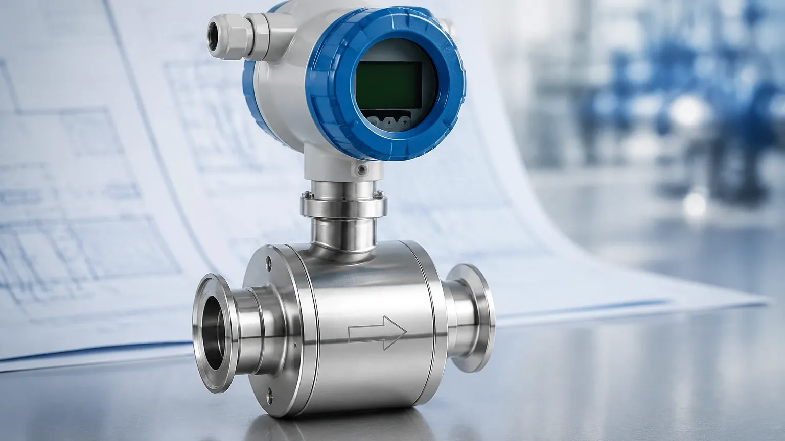
Electromagnetic flow transducers operate based on Faraday’s Law of Electromagnetic Induction. This principle states that a conductor moving through a magnetic field produces an electrical voltage. In this application, the conductive liquid acts as the conductor. As the fluid flows through a magnetic field generated by the transducer’s coils, a voltage is induced that is directly proportional to the velocity of the flow.
Ultrasonic Principle (Transit-Time and Doppler)
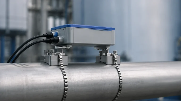
Ultrasonic transducers use sound waves to determine flow velocity.
- Transit-Time: Two sensors send and receive ultrasonic signals. The signal traveling with the flow moves faster than the signal traveling against it. The difference in time is used to calculate velocity.
- Doppler Effect: The transducer reflects sound waves off particles or bubbles in the fluid. The frequency shift of the reflected signal determines the flow rate.
Differential Pressure (DP) Principle
This is one of the oldest and most common methods. By placing a restriction in the pipe (such as an orifice plate or Venturi tube), the transducer creates a pressure drop. According to Bernoulli’s equation, the square root of the pressure difference across the restriction is proportional to the flow rate. The transducer then converts this pressure differential into a flow signal.
Thermal Mass Principle
Thermal flow transducers measure the heat dissipation of a heated element placed in the flow stream. As the fluid passes over the sensor, it carries heat away. The amount of energy required to maintain the temperature difference (or the temperature drop itself) is proportional to the mass flow rate of the fluid.
Technical Selection Criteria
Choosing a flow transducer requires a detailed analysis of the process environment. A mismatch between the technology and the application can lead to rapid sensor degradation or significant measurement errors.
Fluid Properties
The chemical and physical nature of the fluid is the primary constraint.
- Conductivity: Electromagnetic transducers require a minimum conductivity (usually >5 μS/cm). They cannot measure hydrocarbons or deionized water.
- Viscosity: High-viscosity fluids (like heavy oils) may cause significant pressure drops in DP meters or mechanical lag in turbine transducers.
- Solids Content: Abrasive slurries require liners (like PTFE or Neoprene) in electromagnetic meters, while ultrasonic Doppler meters actually require a certain amount of solids to function.
Flow Profile and Reynolds Number
The Reynolds number (Re) determines whether the flow is laminar, transitional, or turbulent. Most flow transducers are calibrated for turbulent flow (Re > 4000). If a process operates in the laminar region, specific transducers, such as certain Coriolis or positive displacement types, may be required to maintain accuracy.
Turndown Ratio
The turndown ratio defines the range over which the transducer can measure accurately. For example, a transducer with a 10:1 turndown ratio and a maximum capacity of 100 m³/h (approx. 440 GPM) can accurately measure down to 10 m³/h (approx. 44 GPM). If your process requires high accuracy at very low flow rates, a high turndown ratio (e.g., 100:1) is necessary.
Selection Comparison Table
| Technology | Fluid Type | Typical Accuracy | Turndown Ratio | Primary Advantage |
| :— | :— | :— | :— | :— |
| Electromagnetic | Conductive Liquids | ±0.5% | 20:1 to 100:1 | No pressure drop; no moving parts |
| Ultrasonic | Clean/Dirty Liquids | ±1.0% to ±2.0% | 10:1 to 50:1 | Non-intrusive (clamp-on) |
| Vortex | Steam, Gas, Liquid | ±1.0% | 10:1 to 20:1 | High temperature/pressure capability |
| Thermal Mass | Clean Gases | ±1.0% | 100:1 | Direct mass flow measurement |
| DP (Orifice) | Liquid, Gas, Steam | ±2.0% | 4:1 | Low cost; well-understood standards |
The Role of Level Measurement in Flow Transduction
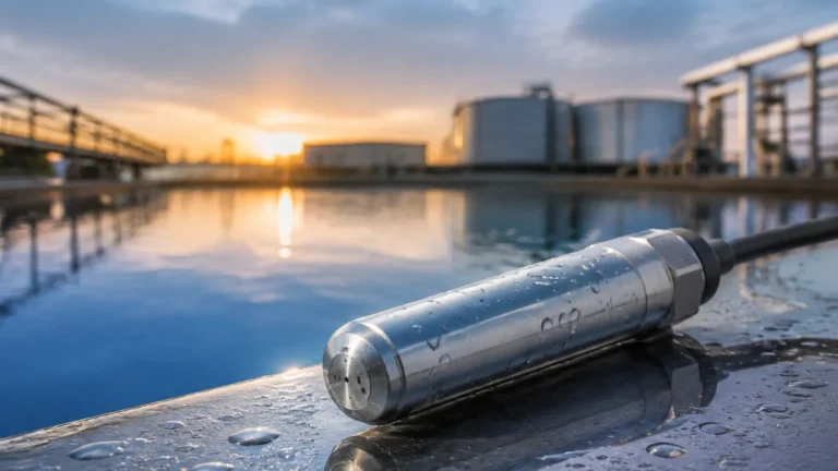
In many industrial settings, particularly in water treatment and environmental monitoring, flow is measured in open channels (flumes and weirs) rather than closed pipes. In these scenarios, a level measurement instrument acts as the primary component of the flow transducer system.
By using an ultrasonic or radar level sensor to measure the "head" (the height of the liquid) behind a weir or within a flume, the flow rate can be calculated using established hydraulic formulas (such as the Manning equation). This is a highly effective method for measuring large volumes of water where pipe-based measurement is impractical. For professionals seeking integrated solutions for these applications, you can Review product options and application support on our Main Page to see how level sensing technology integrates with flow calculation.
Installation Considerations
Even the most accurate flow transducer will fail if installed incorrectly. Engineers must adhere to strict piping requirements to ensure a stable flow profile.
Straight Pipe Runs
Flow transducers generally require a specific length of straight pipe upstream and downstream to eliminate turbulence caused by elbows, valves, or pumps. A common rule of thumb is "10D Upstream and 5D Downstream," where D is the pipe diameter. For example, a 100 mm (approx. 4 inch) pipe would require 1000 mm (approx. 40 inches) of straight pipe before the sensor.
Orientation and Filling
- Horizontal Pipes: Most transducers should be installed such that the pipe is always full. For electromagnetic and ultrasonic types, installing the sensor in a low point or a U-section ensures the pipe remains full even at low flow rates.
- Vertical Pipes: Flow should ideally move upward. This ensures the pipe remains full and prevents air bubbles from being trapped at the sensor head, which would cause signal noise.
Grounding and Interference
Electromagnetic flow transducers are sensitive to electrical noise. Proper grounding of the fluid to the transducer body is essential, especially in plastic or lined pipes. Without a common reference point, the small millivolt signals generated by the flow can be lost in background interference.
Limitations and Common Risks
While flow transducers are robust, they are not universal. Awareness of their limitations prevents premature failure.
1. Entrained Air: Air bubbles are the enemy of most liquid flow transducers. In ultrasonic meters, they scatter the signal; in electromagnetic meters, they are measured as fluid volume, leading to over-reporting of flow.
2. Cavitation: If the pressure at the transducer drops below the vapor pressure of the liquid, vapor bubbles form and collapse. This not only destroys accuracy but can physically pit and erode the sensor internals.
3. Scaling and Coating: In chemical and wastewater applications, buildup on the electrodes or the inner wall of the transducer can insulate the sensor or change the effective pipe diameter, leading to drift in measurement over time.
Frequently Asked Questions (FAQ)
Q: How often should a flow transducer be calibrated?
A: Most industrial standards recommend an annual calibration. However, in critical custody transfer or high-precision chemical dosing, semi-annual checks may be required. If the transducer has no moving parts (like an ultrasonic or mag-meter), calibration stability is generally higher.
Q: Can a flow transducer measure two-phase flow (e.g., liquid and gas)?
A: Most standard transducers are designed for single-phase flow. Measuring a mixture of gas and liquid usually requires specialized Coriolis meters or advanced multiphase flow systems, as standard technologies will produce significant errors.
Q: What is the difference between a transducer and a transmitter?
A: Technically, the transducer senses the physical change, and the transmitter converts that change into a long-distance signal (like 4-20mA). In modern industrial equipment, these are almost always housed in a single unit, and the terms are used interchangeably.
Q: Why is my ultrasonic flow transducer giving inconsistent readings?
A: The most common causes are insufficient straight pipe runs (turbulence), the presence of air bubbles, or a mismatch between the transducer frequency and the pipe material/fluid type. Ensure the sensors are properly coupled to the pipe with acoustic grease if using clamp-on models.
Conclusion
The selection and implementation of a flow transducer require a balance of theoretical knowledge and practical engineering. By understanding the measurement principles—whether electromagnetic, ultrasonic, or pressure-based—and accounting for the specific characteristics of the fluid and the piping system, operators can ensure long-term reliability. For further technical specifications and to explore our full range of measurement instrumentation, visit our Main Page.