E and H
E and H
In the complex landscape of industrial process control, selecting the right level measurement technology is fundamental to operational safety, efficiency, and cost management. Engineers and procurement specialists frequently evaluate high-end instrumentation brands such as e and h (Endress+Hauser) when designing new facilities or upgrading existing infrastructure. Understanding the technical foundations of these instruments is essential for making informed decisions that align with specific application requirements, whether in water treatment, chemical processing, or oil and gas sectors.
This guide provides a comprehensive technical overview of level measurement principles, selection criteria, and practical installation guidance, positioning these technologies within the broader context of global industrial standards. By examining the core physics behind radar, ultrasonic, and hydrostatic measurement, process engineers can better understand the performance benchmarks set by industry leaders like e and h and how to apply these standards to their own equipment selection.
Core Measurement Principles
Before selecting a device, it is critical to understand the physical principles that govern different measurement technologies. Most modern industrial level instruments rely on one of three primary methods: Time-of-Flight (ToF), hydrostatic pressure, or buoyancy.
1. Radar Level Measurement (ToF)
Radar level meters operate on the Time-of-Flight principle. The device emits high-frequency microwave pulses (typically in the 26 GHz or 80 GHz range) toward the surface of the medium. These pulses are reflected back to the sensor. The distance is calculated based on the time interval between transmission and reception.
* 80 GHz Technology: Modern high-frequency radar offers a narrower beam angle, which is particularly useful in vessels with internal obstructions like agitators or heating coils. This precision is a hallmark of premium instruments often compared to the e and h Micropilot series.
* 26 GHz Technology: This is often preferred for applications involving heavy dust or steam, where a slightly wider beam can provide more reliable surface detection.
2. Ultrasonic Level Measurement
Ultrasonic sensors emit mechanical sound waves. Like radar, they use the ToF principle. However, because sound requires a medium to travel through, its speed is significantly affected by air temperature, pressure, and gas composition. Most high-quality ultrasonic transmitters include integrated temperature sensors to compensate for these variations automatically.
3. Hydrostatic Level Measurement
Hydrostatic transmitters measure the pressure exerted by a liquid column. The formula $P = \rho \times g \times h$ (where $P$ is pressure, $\rho$ is density, $g$ is gravity, and $h$ is height) allows the transmitter to calculate the level. This method is highly reliable for vented tanks but requires careful consideration of the fluid's specific gravity.
4. Magnetic Level Gauges
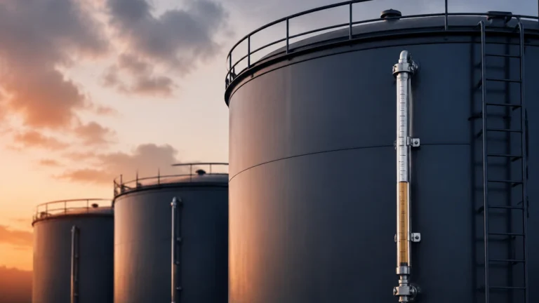
Operating on the buoyancy principle, magnetic level gauges use a float containing a permanent magnet. As the liquid level rises or falls, the float moves accordingly, flipping magnetic flaps on an external scale or triggering a reed-chain transmitter for remote monitoring. This provides a clear visual indication without requiring power.
Key Evaluation Criteria for Level Instruments
When evaluating instruments, whether from a specialized manufacturer or a global giant like e and h, several technical factors must be prioritized to ensure long-term reliability.
Media Characteristics
The chemical compatibility of the wetted parts is the first hurdle. For corrosive acids, PTFE or PVDF coatings are mandatory. For food and beverage applications, 316L stainless steel with hygienic connections (such as Tri-Clamp) is standard. Additionally, the dielectric constant ($ε_r$) of the medium is vital for radar measurement; fluids with low $ε_r$, like hydrocarbons, reflect less energy than water-based fluids.
Process Conditions
* Temperature: Standard sensors typically handle up to 80°C, but specialized high-temperature versions can withstand over 250°C.
* Pressure: Hydrostatic and radar sensors are often rated for high-pressure vessels, whereas ultrasonic sensors are generally limited to near-atmospheric conditions.
* Turbulence and Foam: Heavy foam can absorb ultrasonic and radar signals. In such cases, guided wave radar or hydrostatic sensors are often more effective.
Accuracy and Repeatability
In custody transfer or high-value chemical dosing, accuracy within ±1 mm or ±2 mm is required. For simple pump control in water treatment, ±5 mm to ±10 mm is usually sufficient. Understanding these requirements helps in choosing between a high-precision radar and a more cost-effective ultrasonic unit.
Practical Selection Table
The following table summarizes the typical application ranges for common level measurement technologies.
| Technology | Typical Accuracy | Max Range | Media Type | Key Limitation |
| :— | :— | :— | :— | :— |
| 80 GHz Radar | ±1 mm to ±3 mm | 30m – 120m | Liquids & Solids | High initial cost |
| Ultrasonic | ±0.25% of range | 15m – 20m | Liquids & Slurries | Affected by foam/vacuum |
| Hydrostatic | ±0.1% to ±0.5% | 200m (Cable) | Liquids only | Density must be constant |
| Magnetic Gauge| ±5 mm to ±10 mm | 6m (Sectional) | Liquids only | Moving parts can clog |
For a broader look at available industrial solutions and technical specifications, engineers should consult the Main Page for detailed product comparisons.
Installation Considerations and Best Practices
Even the highest quality instrument, such as those produced by e and h, will fail if installed incorrectly. Engineering teams must adhere to strict installation protocols.
1. Nozzle Geometry: For radar and ultrasonic sensors, the nozzle should be as short and wide as possible to prevent "ringing" or false echoes from the nozzle wall. The sensor face should typically extend slightly into the tank.
2. Obstruction Clearance: Ensure the signal beam path is clear of ladders, pipes, or agitators. If obstructions are unavoidable, most modern transmitters offer "false echo suppression" or "mapping" to ignore these fixed signals.
3. Hydrostatic Positioning: Submersible hydrostatic sensors should be placed in an area of low turbulence. In tanks with agitators, using a stilling well or a protective pipe is recommended to prevent mechanical damage to the diaphragm.
4. Dead Zones: Every non-contact sensor has a "blocking distance" or dead zone near the sensor face where measurement is impossible. Ensure the maximum expected liquid level does not enter this zone.

Limitations and Common Risks
While industrial level meters are highly advanced, they are not universal solutions. Each technology has inherent physical limitations.
* Vapor and Gas Layers: In pressurized chemical tanks, the gas layer above the liquid can change density, affecting the speed of sound (ultrasonic) or even the speed of light (radar, though to a much lesser extent). This can lead to measurement errors if not compensated.
* Build-up and Coating: In wastewater or cement silos, material build-up on the sensor face can attenuate the signal. While some radar sensors can "see through" thin layers of build-up, heavy coating will eventually cause a signal loss.
* Vacuum Conditions: Ultrasonic waves cannot travel through a vacuum. For vacuum distillation columns, radar or hydrostatic transmitters are the only viable options.
The Industry Standard Context: e and h
In the B2B sector, e and h is often viewed as the benchmark for documentation, digital integration (such as Heartbeat Technology), and HART/Profibus communication protocols. When engineers specify "e and h quality," they are usually looking for:
* Reliability: Long Mean Time Between Failures (MTBF).
* Traceability: Calibration certificates and material test reports (MTRs).
* Integration: Seamless connection to PLC and SCADA systems.
Manufacturers like Welk aim to provide this same level of technical rigor and reliability, offering cost-effective alternatives that meet the same stringent industrial requirements for accuracy and durability in harsh environments.
Frequently Asked Questions (FAQs)
Q: Can I use radar for solids measurement?
A: Yes, 80 GHz radar is excellent for solids like grain, cement, or plastic pellets. It handles the low dielectric constant and uneven surface of solids much better than ultrasonic technology.
Q: How often do hydrostatic sensors need calibration?
A: In stable environments, hydrostatic sensors are very reliable. However, in applications with fluctuating temperatures or corrosive media, an annual calibration check is recommended to account for potential diaphragm drift.
Q: What is the benefit of a 2-wire vs. 4-wire transmitter?
A: 2-wire transmitters are powered by the 4-20mA loop, simplifying wiring and reducing costs. 4-wire transmitters have a separate power supply, which is often necessary for high-power devices like certain radar units or those with integrated heaters for cold climates.
Q: Does foam always stop a radar signal?
A: Not necessarily. While thick, dry foam can absorb radar pulses, many guided wave radar (GWR) units can penetrate foam to measure the liquid level beneath, or detect the top of the foam layer if required.
Conclusion
Selecting level measurement instrumentation requires a balance between technical necessity and budgetary constraints. While brands like e and h provide a high standard of excellence, the fundamental engineering principles remain the same across the industry. By focusing on media properties, process conditions, and proper installation, engineers can implement reliable level control systems that ensure the safety and productivity of their operations. For further technical support and to review specific instrument options, please visit the Main Page to explore our full range of industrial measurement solutions.