Ultrasonic Flow Meter How It Works
Ultrasonic Flow Meter How It Works
In the realm of industrial process control, the ability to measure fluid flow accurately without interrupting the process or compromising the integrity of the piping system is a significant advantage. Ultrasonic flow meters have emerged as a primary solution for these requirements. Unlike traditional mechanical meters that rely on moving parts—which are prone to wear and pressure drops—ultrasonic technology utilizes sound waves to determine the velocity of a liquid. This guide provides a comprehensive technical overview of ultrasonic flow meter how it works, their underlying physics, and the practical considerations for their implementation in B2B industrial environments.
Fundamental Principles of Ultrasonic Flow Measurement
To understand an ultrasonic flow meter how it works, one must first understand the behavior of high-frequency sound waves in a moving medium. These instruments typically operate at frequencies between 0.5 MHz and 4 MHz. There are two primary methods used to calculate flow: Transit-Time and Doppler Effect. While both use ultrasonic transducers, they are suited for different fluid conditions.
The Transit-Time Principle
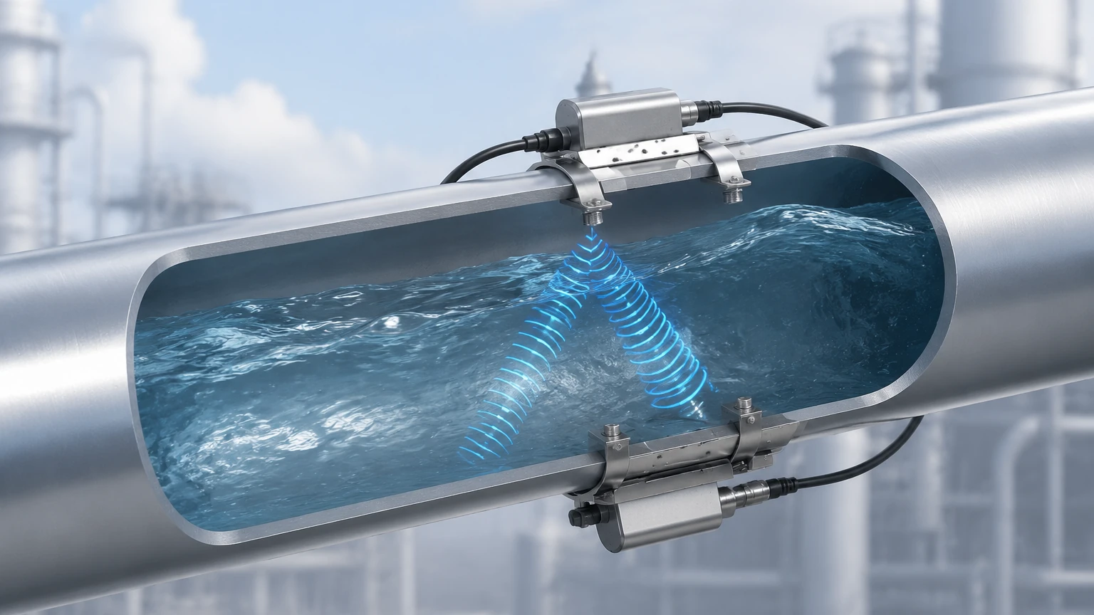
The transit-time method is the most common technology used for clean liquids. It relies on the fact that a sound wave traveling in the direction of fluid flow will move faster than a sound wave traveling against the flow.
Two transducers (A and B) function as both transmitters and receivers. Transducer A sends a signal to Transducer B (downstream), and then Transducer B sends a signal back to Transducer A (upstream). If the fluid is stationary, the time taken for the signal to travel in both directions is identical. However, when the fluid is moving, the downstream signal is accelerated by the flow, and the upstream signal is retarded.
The difference in these transit times ($Δt$) is directly proportional to the velocity of the fluid. By knowing the pipe's cross-sectional area and the fluid velocity, the meter calculates the volumetric flow rate. This method requires a relatively clean fluid with low concentrations of bubbles or suspended solids to ensure the sound wave can pass through the medium without excessive scattering.
The Doppler Effect Principle
The Doppler flow meter operates on the principle of frequency shift. When an ultrasonic beam is transmitted into a moving liquid, it reflects off discontinuities such as suspended particles, entrained gas bubbles, or even turbulence within the fluid.
According to the Doppler effect, the frequency of the reflected signal is shifted relative to the transmitted frequency. If the particles are moving toward the transducer, the frequency increases; if they move away, the frequency decreases. The magnitude of this frequency shift is proportional to the velocity of the reflectors. Unlike transit-time meters, Doppler meters require a minimum concentration of "reflectors" (typically at least 100 ppm of particles or bubbles larger than 100 microns) to function correctly.
Transit-Time vs. Doppler: Understanding the Technology
Choosing the right technology depends heavily on the fluid characteristics. The following table outlines the primary differences and application suitability:
| Feature | Transit-Time Flow Meter | Doppler Flow Meter |
| :— | :— | :— |
| Ideal Fluid | Clean liquids (water, oils, chemicals) | Dirty liquids, slurries, aerated liquids |
| Suspended Solids | < 2% by volume | > 100 ppm (minimum required) |
| Accuracy | High (typically 0.5% to 2%) | Moderate (typically 2% to 5%) |
| Pipe Sizes | 10 mm to 5000 mm | 25 mm to 5000 mm |
| Key Advantage | High precision in clean fluids | Capable of measuring "difficult" fluids |
For engineers evaluating these technologies for specific projects, reviewing the Main Page of a professional manufacturer like Welk is essential to identify which sensor configuration matches the specific chemical and physical properties of the process medium.
Technical Components and Signal Processing
An ultrasonic flow meter is comprised of two main components: the transducers and the electronic transmitter (converter).
Transducers and the Piezoelectric Effect
The heart of the transducer is a piezoelectric crystal. When an electrical pulse is applied to the crystal, it vibrates at a high frequency, generating ultrasonic waves. Conversely, when a returning sound wave hits the crystal, it generates an electrical signal. In clamp-on systems, these transducers are mounted to the outside of the pipe using a coupling agent (such as grease or gel) to eliminate air gaps that would otherwise reflect the sound energy.
Signal Processing and DSP
Modern meters use Digital Signal Processing (DSP) to filter out noise caused by industrial machinery or pipe vibrations. The transmitter calculates the flow velocity using complex algorithms that account for the Reynolds Number, which compensates for the flow profile (laminar vs. turbulent). This ensures that the velocity measured at the pipe wall or across a specific path is accurately converted into the average velocity of the entire fluid column.
Practical Selection Criteria for Industrial Applications
When specifying an ultrasonic flow meter, several technical parameters must be confirmed to ensure reliable performance.
1. Pipe Material and Liner: Ultrasonic waves must pass through the pipe wall. While metals (carbon steel, stainless steel, ductile iron) and most plastics are excellent conductors of sound, pipes with internal liners (like rubber or cement) or heavily corroded interiors can attenuate or scatter the signal.
2. Fluid Temperature: Transducers have specific temperature ratings. High-temperature applications (above 150°C) require specialized high-temperature sensors and mounting hardware.
3. Flow Range and Velocity: Ensure the expected flow velocity falls within the meter's measurable range (typically 0.1 m/s to 12 m/s).
4. Pressure Requirements: For inline (wetted) ultrasonic meters, the pressure rating of the flow cell must exceed the maximum process pressure. Clamp-on meters are generally immune to pressure constraints as they do not contact the fluid.
Installation Guidelines and Best Practices
The accuracy of an ultrasonic flow meter is highly dependent on the installation environment. Because the meter measures velocity, it requires a stable, fully developed flow profile.
Straight Pipe Runs
To avoid turbulence caused by valves, pumps, or elbows, the meter should be installed in a straight section of pipe. The standard industry recommendation is:
* Upstream: At least 10 pipe diameters (10D) of straight pipe.
* Downstream: At least 5 pipe diameters (5D) of straight pipe.
Transducer Mounting Methods
There are three common mounting configurations for clamp-on transducers:
* V-Method: The signal traverses the pipe twice, reflecting off the opposite wall. This is the standard for pipes ranging from 25 mm to 400 mm.
* Z-Method: Transducers are mounted on opposite sides of the pipe, and the signal traverses the pipe once. This is used for large pipes (above 400 mm) or where signal attenuation is high.
* W-Method: The signal traverses the pipe four times. This is used for very small pipes (below 50 mm) to increase the transit time and improve resolution.
Orientation
Transducers should ideally be mounted in the 3 o'clock and 9 o'clock positions on a horizontal pipe. Mounting at the top (12 o'clock) can lead to signal loss if air bubbles collect there, while mounting at the bottom (6 o'clock) may be affected by sediment buildup.
Limitations and Troubleshooting Common Challenges
While ultrasonic flow meters are versatile, they are not universal solutions. Understanding their limitations is key to avoiding project failures.
* Signal Attenuation: If the fluid contains too many bubbles or solids for a transit-time meter, the signal will be lost. Conversely, if a Doppler meter is used on pure, deionized water, there will be no reflections to measure.
* Acoustic Short-Circuiting: In some metal pipes, the sound may travel through the pipe wall faster than through the fluid, creating a "false" signal. Advanced meters use time-gating to ignore these wall-borne signals.
* Coupling Failure: Over time, the coupling gel between a clamp-on transducer and the pipe can dry out or wash away, leading to a "No Signal" error. Permanent installations often use solid epoxy or mechanical tensioning to prevent this.
Frequently Asked Questions (FAQ)
Q: Can ultrasonic flow meters measure gas flow?
A: Yes, but gas measurement requires much higher energy transducers because gases are much less dense than liquids and attenuate sound waves significantly. Most standard industrial ultrasonic meters are designed specifically for liquids.
Q: Do I need to cut the pipe to install a clamp-on meter?
A: No. One of the primary benefits of clamp-on technology is that it requires no pipe cutting and no process downtime. This makes them ideal for retrofitting and temporary flow surveys.
Q: How does pipe scaling affect measurement?
A: Internal scaling or lime buildup acts as an additional layer that the sound must penetrate. If the scale is thick or contains air pockets, it can block the ultrasonic signal entirely. In such cases, the pipe must be cleaned, or an inline meter should be used.
Q: What is the maintenance requirement for these meters?
A: Since there are no moving parts, maintenance is minimal. For clamp-on models, periodic inspection of the transducer coupling and signal strength is recommended. For inline models, maintenance is similar to other static piping components.
Conclusion
Ultrasonic flow meters represent a sophisticated, non-invasive approach to fluid measurement that aligns with the needs of modern industrial automation. By leveraging the transit-time or Doppler principles, these instruments provide reliable data across a wide range of applications, from municipal water treatment to complex chemical processing.
When planning a measurement system, engineers should confirm the fluid properties, pipe conditions, and required accuracy levels. For those seeking specialized hardware or customized OEM/ODM solutions, visiting the Main Page provides access to a broad portfolio of industrial level and flow measurement instruments designed to meet rigorous global standards. By adhering to proper installation practices and selecting the correct ultrasonic technology, facilities can achieve long-term, maintenance-free flow monitoring.