Compressed Air Energy Efficiency
Compressed Air Energy Efficiency
Compressed air is often referred to as the "fourth utility" in industrial environments, alongside electricity, water, and natural gas. However, it is frequently the most expensive utility to produce. In a typical industrial facility, compressed air can account for up to 10% to 30% of total electricity consumption. Despite its importance, the efficiency of these systems is notoriously low; often, only 10% to 15% of the electrical energy used by a compressor is converted into useful work at the point of use. The remaining energy is largely dissipated as heat.
Improving compressed air energy efficiency is not merely a matter of purchasing a more efficient compressor. It requires a comprehensive approach to system management, including leak detection, pressure stabilization, and, crucially, effective condensate management. Level measurement instrumentation plays a vital role in this optimization by ensuring that moisture and contaminants are removed from the system without wasting the compressed air itself.
The Physics of Compressed Air and Energy Loss
To understand how to improve efficiency, one must first understand the relationship between pressure, temperature, and volume. When air is compressed, its temperature rises significantly. This heat is energy that is often lost to the environment through intercoolers and aftercoolers. Furthermore, air naturally contains water vapor. As air is compressed and subsequently cooled, this vapor condenses into liquid water.
If this condensate is not managed correctly, it creates several efficiency-draining problems:
1. Reduced Storage Capacity: Water buildup in receiver tanks reduces the volume available for air storage, causing the compressor to cycle more frequently.
2. Increased Pressure Drop: Liquid water in piping increases friction and creates blockages, forcing the compressor to run at a higher discharge pressure to maintain the required pressure at the end-use tool.
3. Equipment Damage: Moisture leads to corrosion in pipes and pneumatic tools, increasing the frequency of leaks and maintenance requirements.
By utilizing precise level measurement to manage these fluids, plants can significantly enhance their compressed air energy efficiency.
Measurement Principles for Efficiency Optimization
Before selecting instrumentation for a compressed air system, it is essential to understand the physical principles governing different measurement technologies. In the context of compressed air, level sensors are primarily used in receiver tanks, oil-water separators, and condensate drain traps.
Radar Level Measurement
Radar level meters operate on the principle of Time Domain Reflectometry (TDR) or Frequency Modulated Continuous Wave (FMCW). The sensor emits high-frequency electromagnetic pulses that travel at the speed of light. When these pulses hit the surface of the liquid (condensate or oil), they are reflected back to the sensor. The distance is calculated based on the time of flight. Radar is highly effective in compressed air systems because it is unaffected by changes in pressure, temperature, or the density of the gas above the liquid.
Ultrasonic Level Measurement
Ultrasonic sensors use sound waves rather than electromagnetic waves. The sensor emits a sound pulse that reflects off the liquid surface. The time it takes for the echo to return determines the level. While cost-effective, ultrasonic sensors are sensitive to the composition of the medium through which the sound travels. In high-pressure compressed air environments, the speed of sound changes, requiring temperature and pressure compensation to maintain accuracy.
Hydrostatic Level Transmitters
These sensors measure the pressure exerted by the liquid column. In a pressurized tank, a differential pressure approach is required to subtract the overhead air pressure from the total pressure at the bottom of the tank. This provides a direct measurement of the liquid height. Hydrostatic sensors are robust but require careful installation to ensure the pressure ports do not become clogged with oily sludge common in air systems.
Level Switches (Float and Capacitance)
Level switches are used for point-level detection—specifically for high-level alarms or to trigger the opening of a drain valve. Magnetic float switches rely on a buoyancy principle, where a float moves with the liquid level to actuate a reed switch. Capacitance switches detect changes in the electrical capacitance between the probe and the tank wall as the liquid rises.
Selection Criteria for Level Instrumentation
Choosing the right technology depends on the specific point in the compressed air circuit. The following table provides a guide for typical applications within an industrial air system.
| Application Point | Recommended Technology | Why? |
| :— | :— | :— |
| Main Receiver Tank | Radar or Hydrostatic | Requires high accuracy over a large range; must handle pressure fluctuations. |
| Condensate Drain Trap | Capacitive or Float Switch | Needs to trigger rapid discharge cycles; must be compact and reliable. |
| Oil-Water Separator | Ultrasonic or Radar | Non-contact measurement prevents fouling from oily residue. |
| Intercoolers | Level Switch | Critical for preventing water carryover into the next compression stage. |
| Refrigerated Dryers | Capacitive Switch | High sensitivity to small amounts of moisture in a compact space. |
When evaluating these options, engineers must consider the operating pressure (often 7 to 10 bar, but can be much higher), the presence of lubricants (oil carryover), and the required accuracy for the control system.
Installation and Maintenance Best Practices
Proper installation is critical to ensuring that level measurement contributes to compressed air energy efficiency rather than becoming a point of failure.
1. Positioning and Orientation
For ultrasonic and radar sensors, the device must be mounted perpendicular to the liquid surface. In receiver tanks, avoid mounting sensors directly above the inlet pipe, as the turbulence from incoming air can cause false readings. If the tank has internal baffles or cooling coils, radar sensors with a narrow beam angle should be used to avoid interference.
2. Pressure and Temperature Limits
Ensure that all wetted parts of the sensor—including gaskets and seals—are rated for the maximum discharge temperature and pressure of the compressor. For hydrostatic sensors, the diaphragm material must be compatible with the synthetic oils often used in screw compressors.
3. Management of Condensate Drains
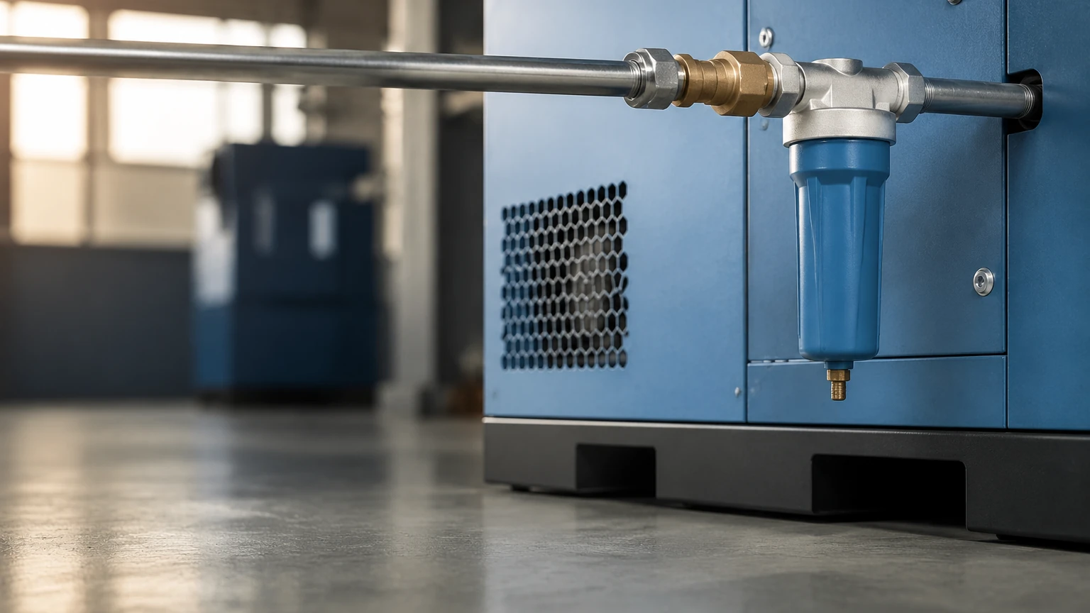
One of the most significant energy wastes in a compressed air system is the "timer-based" drain valve. These valves open at set intervals regardless of whether water is present, often releasing large volumes of expensive compressed air. By installing a level-controlled drain—using a level switch or continuous sensor—the valve only opens when liquid is present, eliminating air loss and significantly improving system efficiency.
4. Calibration and Verification
Level sensors should be calibrated annually. In systems with high oil carryover, sensors should be inspected every six months for buildup. A fouled sensor can lead to a "failed closed" state, where water backs up into the system, or a "failed open" state, where air is constantly leaked to the atmosphere.
Risks and Limitations in Compressed Air Monitoring
While level measurement is a powerful tool, engineers must be aware of specific technical limitations:
* Foaming: In oil-water separators, the condensate can foam. This can confuse ultrasonic sensors, which may see the top of the foam as the liquid level. Radar or specialized capacitance probes are better suited for these environments.
* Dielectric Constants: Radar sensors depend on the dielectric constant of the liquid. While water has a high dielectric constant (approx. 80), compressor oil is much lower (approx. 2). In separators where the two liquids are present, the sensor must be capable of distinguishing between the layers or measuring the overall interface.
* Pressure Fluctuations: Rapid changes in pressure can affect the accuracy of hydrostatic and ultrasonic sensors. Using damped electronics or software filters can help mitigate these effects.
Frequently Asked Questions (FAQs)
Q: How does level measurement directly save energy in a compressed air system?
A: It primarily saves energy by enabling "zero-loss" condensate drainage. Instead of venting air through a timed valve, level sensors ensure only liquid is discharged. Additionally, it prevents water buildup that would otherwise reduce the effective volume of receiver tanks, preventing compressor short-cycling.
Q: Can I use a standard water level sensor for compressor condensate?
A: Not always. Compressor condensate is often an emulsion of water and oil. This can coat sensors. You must ensure the sensor is rated for oily environments and can handle the specific operating pressures of your system (typically 0.7 MPa to 1.3 MPa for standard industrial use).
Q: What is the impact of moisture on compressed air energy efficiency?
A: Moisture increases the density of the air-stream and creates higher pressure drops across filters and dryers. For every 0.1 bar of pressure drop caused by moisture or clogged filters, the compressor must consume approximately 1% more energy to maintain the same system pressure.
Conclusion
Optimizing compressed air energy efficiency is a continuous process that relies on accurate data and reliable control. Level measurement instrumentation is a cornerstone of this effort, providing the necessary feedback to manage condensate effectively and protect downstream equipment. By selecting the appropriate measurement principle—whether it be radar for high-pressure receivers or capacitive switches for zero-loss drains—industrial facilities can significantly reduce their utility costs and carbon footprint.
For professional-grade instrumentation designed to withstand the rigors of industrial air systems, including radar, ultrasonic, and hydrostatic solutions, engineers can review product options and application support on the Welk Main Page. Implementing precise level control is one of the most cost-effective steps toward a truly efficient compressed air system.