Pressure Transmitter in Sensor
Pressure Transmitter in Sensor
In the field of industrial process control, the accurate measurement of liquid levels and fluid pressures is fundamental to operational safety and efficiency. A critical component in these systems is the integrated assembly often referred to as a pressure transmitter in sensor. While the terms "sensor" and "transmitter" are sometimes used interchangeably in casual conversation, in a professional engineering context, they represent two distinct yet integrated functions within a single device. A sensor is the primary element that detects a physical change—in this case, pressure—and converts it into an electrical signal. The transmitter then takes that raw signal, amplifies it, compensates for environmental variables, and converts it into a standardized output suitable for long-distance transmission to a PLC (Programmable Logic Controller) or DCS (Distributed Control System).
Welk, as a professional manufacturer of industrial level measurement instruments, specializes in optimizing this integration to ensure reliability in demanding environments such as water treatment, chemical processing, and oil and gas operations. Understanding the nuances of how a pressure transmitter in sensor functions is essential for engineers tasked with selecting the right instrumentation for their specific application.
Measurement Principles of Pressure Transmitters
Before selecting a device, it is vital to understand the physics governing its operation. Most pressure transmitters used for level measurement rely on the principle of hydrostatic pressure.
The Hydrostatic Principle
The hydrostatic pressure ($P$) at a specific depth in a static liquid is directly proportional to the height ($h$) of the liquid column above it, the density ($ρ$) of the liquid, and the gravitational constant ($g$). The formula is expressed as:
$$P = ρ · g · h$$
In practical terms, if the density of the fluid remains constant, the pressure measured by the pressure transmitter in sensor at the bottom of a tank provides a direct and accurate calculation of the liquid level. This method is widely favored because it is independent of tank shape or volume; it only cares about the vertical height of the liquid.
Gauge vs. Absolute Pressure
When measuring level in an open tank, the sensor must account for atmospheric pressure acting on the surface of the liquid. To achieve this, a gauge pressure transmitter is used. These devices often feature a vented cable or a reference port that allows the internal side of the sensing diaphragm to be exposed to the current atmospheric pressure, effectively "zeroing out" the air pressure and measuring only the weight of the liquid. Conversely, in sealed or pressurized vessels, an absolute pressure sensor or a differential pressure (DP) transmitter may be required to subtract the internal tank pressure from the total pressure measured at the bottom.
Anatomy of the Pressure Transmitter in Sensor
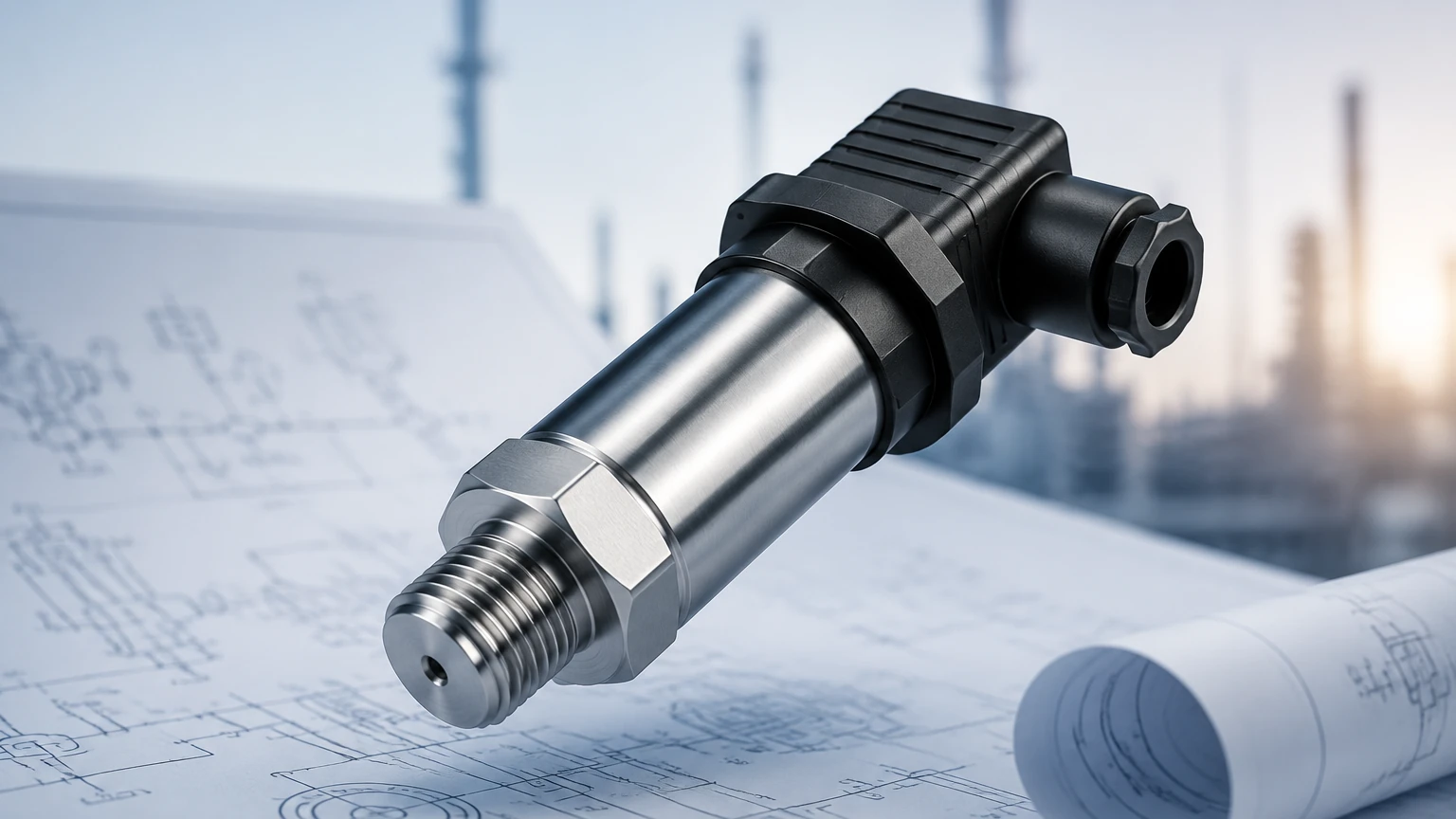
The modern pressure transmitter in sensor consists of several sophisticated layers designed to protect the delicate electronics while maintaining high sensitivity.
1. The Sensing Element (The Sensor): This is the heart of the device. Common technologies include piezoresistive silicon and ceramic capacitive sensors. Piezoresistive sensors utilize a silicon strain gauge bonded to a diaphragm; when pressure is applied, the diaphragm deforms, changing the electrical resistance. Ceramic capacitive sensors measure changes in capacitance between a ceramic diaphragm and a fixed substrate.
2. The Isolation Diaphragm: To prevent corrosive process fluids from damaging the sensing element, a thin, flexible isolation diaphragm (often made of 316L stainless steel, Hastelloy, or Tantalum) is used. The space between the isolation diaphragm and the sensor is filled with a transfer fluid, typically silicone oil.
3. The Signal Conditioning Circuit (The Transmitter): This electronic module converts the millivolt signal from the sensor into a standard industrial signal, such as 4-20mA, 0-10V, or digital protocols like HART or Modbus. This stage also includes temperature compensation, as the physical properties of the sensing element can shift with thermal changes.
Practical Selection Criteria
Choosing the correct pressure transmitter in sensor requires a detailed analysis of the application environment. Engineers should consult the Main Page of reputable manufacturers to review specific technical datasheets, but the following table provides a general comparison of common configurations.
Selection Table: Submersible vs. External Transmitters
| Feature | Submersible (Level Probe) | External (Pipe-Mounted) |
| :— | :— | :— |
| Installation Point | Dropped into the tank/well | Mounted to a flange or pipe at the base |
| Primary Use Case | Deep wells, reservoirs, open sumps | Pressurized tanks, chemical reactors |
| Maintenance Access | Requires pulling the cable up | Accessible via isolation valves |
| Material | Usually 316SS with specialized cable (PUR/PE) | Wide range of alloys and coatings |
| Protection Rating | IP68 (Permanent submersion) | IP65/IP67 (Weatherproof) |
Key Evaluation Factors
* Chemical Compatibility: The wetted materials must be resistant to the process fluid. For example, while 316L stainless steel is standard for water, hydrochloric acid applications might require a ceramic sensor with a PVDF housing.
* Accuracy and Stability: For inventory management, high-accuracy sensors (0.1% FS) are necessary. For simple pump control, 0.5% FS may suffice.
* Pressure Range: The sensor should be rated for a range slightly higher than the maximum expected liquid height to prevent damage from pressure surges (water hammer).
Installation Considerations
Proper installation is as important as the device selection itself. Even the highest quality pressure transmitter in sensor will fail or provide inaccurate data if installed incorrectly.
Submersible Installation
When installing a submersible transmitter, the cable must be secured to prevent the sensor from moving due to turbulence. In deep wells or fast-moving water, a stilling well (a perforated pipe) should be used to shield the sensor. Furthermore, the vented cable must terminate in a dry environment or a junction box with a desiccant filter to prevent moisture from entering the vent tube and causing internal corrosion or measurement drift.
External Installation
For transmitters mounted to the side of a tank, the use of an isolation valve is mandatory. This allows for the removal and calibration of the sensor without draining the entire vessel. The mounting position should be low enough to capture the full range of the liquid but high enough to avoid the accumulation of sediment or sludge that could clog the diaphragm.
Limitations and Challenges
While highly reliable, hydrostatic pressure measurement has inherent limitations:
* Density Sensitivity: Since the transmitter measures weight, any change in the liquid's density (caused by temperature fluctuations or changes in chemical concentration) will be interpreted as a change in level. In applications with significant temperature swings, integrated temperature sensors can be used to provide density correction via the PLC.
* Mechanical Damage: The isolation diaphragms are extremely thin. Abrasive particles in a slurry or high-pressure cleaning jets can easily dent or rupture the diaphragm.
* Clogging: In wastewater or viscous fluids, the pressure port can become blocked. For these applications, a "flush diaphragm" design is recommended, where the sensing surface is flat and even with the process connection, preventing material buildup.
Frequently Asked Questions (FAQs)
Q: Can a pressure transmitter in sensor be used for boiling liquids?
A: It is challenging. Boiling liquids have fluctuating densities and the vapor pressure in the headspace of the tank will interfere with a standard gauge pressure reading. A differential pressure transmitter is usually required in these scenarios.
Q: How often should these sensors be calibrated?
A: Most industrial-grade transmitters from Welk offer excellent long-term stability. However, for critical applications, an annual calibration check is standard practice. Many modern digital transmitters allow for "field zeroing" to account for minor shifts over time.
Q: What is the difference between a 2-wire and a 4-wire transmitter?
A: A 2-wire transmitter uses the same pair of wires for both power supply and signal transmission (4-20mA loop), making it highly efficient for wiring. A 4-wire transmitter uses separate pairs for power and signal, which is often necessary for devices with high power consumption, such as those with integrated heaters or local displays.
Conclusion
The integration of a pressure transmitter in sensor represents a pinnacle of practical engineering, combining sensitive physical detection with robust electronic communication. By understanding the hydrostatic principles, selecting the appropriate materials, and adhering to strict installation guidelines, industrial operators can achieve precise and reliable level measurement for years. For those seeking to explore specific product options or requiring application-specific support, it is recommended to consult with technical experts and review comprehensive product catalogs to ensure the chosen instrumentation aligns with both the technical requirements and the safety standards of the facility.