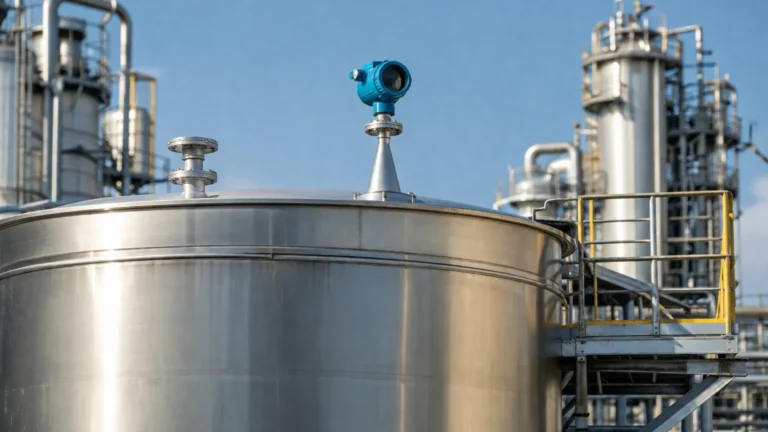
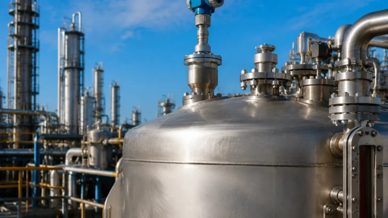
Radar Level Transmitter Non Contact
Engineering Guide to Radar Level Transmitter Non Contact Technology
In the landscape of industrial process control, accurate level measurement is a fundamental requirement for safety, inventory management, and process efficiency. Among the various technologies available, the radar level transmitter non contact type has emerged as a preferred solution for challenging environments. Unlike traditional mechanical or contact-based sensors, non-contact radar devices utilize electromagnetic waves to determine the distance to a product surface without physical interaction. This engineering guide explores the principles, selection criteria, and installation best practices for Radar Level Meters in modern B2B industrial applications.
1. Measurement Principles: How Non-Contact Radar Works
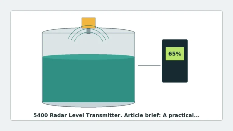
Non-contact radar level transmitters operate on the principle of "Time of Flight" (ToF). The device, typically mounted at the top of a tank or vessel, emits a high-frequency electromagnetic signal toward the material below. This signal travels at the speed of light, reflects off the surface of the medium, and returns to the sensor's antenna.
Pulse Radar vs. FMCW
There are two primary methods used by a radar level transmitter non contact to calculate distance:
1. Pulse Radar: The transmitter sends out a short microwave pulse and measures the time it takes for the pulse to return. This is a straightforward time-delay measurement. While cost-effective, it may struggle with low-dielectric materials or extremely turbulent surfaces.
2. FMCW (Frequency Modulated Continuous Wave): The transmitter emits a continuous signal with a constantly changing frequency. The difference in frequency between the emitted signal and the reflected signal is proportional to the distance. FMCW is generally more accurate and provides a better signal-to-noise ratio, making it suitable for complex industrial tanks with internal obstructions.
Frequency Bands
The performance of a radar level transmitter non contact is heavily influenced by its operating frequency. Common industrial frequencies include:
* 6 GHz (C-Band): Historically used for applications with heavy foam or steam, as the longer wavelength can penetrate these obstacles more effectively. However, it requires larger antennas and has a wide beam angle.
* 26 GHz (K-Band): The industry workhorse. It offers a balance between antenna size and beam focus, suitable for most medium-sized tanks.
* 80 GHz (W-Band): The modern standard for high precision. The short wavelength allows for very small antennas and a narrow beam angle (often as small as 3°), which is ideal for avoiding internal tank structures like agitators or ladders.
2. Selection Criteria for Industrial Applications
Choosing the right radar level transmitter non contact requires a thorough analysis of the process medium and the vessel environment. Engineers must consider the following factors to ensure long-term reliability.
Dielectric Constant (εr)
The reflectivity of the radar signal depends on the dielectric constant of the material. Materials with high dielectric constants (e.g., water, εr ≈ 80) reflect signals strongly. Materials with low dielectric constants (e.g., hydrocarbons, εr < 2) reflect very little energy, requiring more sensitive electronics and potentially FMCW technology to ensure a stable reading.
Process Temperature and Pressure
Standard radar sensors are often rated for temperatures up to 150°C (302°F) and pressures up to 40 bar (580 psi). However, specialized versions from manufacturers like Welk can handle extreme conditions, such as molten salts or high-pressure reactors, by using specialized antenna materials like PTFE or ceramic glass seals.
Vessel Geometry and Internal Obstructions
In narrow tanks or vessels with internal heating coils, agitators, and baffles, the beam angle is critical. A wide beam will reflect off these obstructions, creating "false echoes." In these scenarios, an 80 GHz radar level transmitter non contact is recommended due to its narrow focus, which can "thread the needle" between obstructions.
| Feature | 26 GHz Radar | 80 GHz Radar |
| :— | :— | :— |
| Beam Angle | 8° to 20° | 3° to 6° |
| Accuracy | ±3 mm to ±5 mm | ±1 mm to ±2 mm |
| Antenna Size | Larger (Horn/Flange) | Compact (Lens/Small Horn) |
| Dust/Steam Resistance | Moderate | High |
| Application | Large storage tanks | Process vessels with agitators |
3. Installation Considerations and Constraints
Correct installation is the most significant factor in the performance of a radar level transmitter non contact. Even the most advanced sensor will fail if placed incorrectly.
The Dead Zone (Blocking Distance)
Every radar sensor has a "dead zone" or blocking distance near the antenna where measurement is not possible. This is typically between 50 mm and 300 mm (2 to 12 inches). Engineers must ensure the maximum fill level of the tank does not enter this zone, or the sensor will lose the signal or report an error.
Nozzle Design
The mounting nozzle should be as short as possible. If the nozzle is too long or narrow, the radar signal will reflect off the nozzle walls before even entering the tank, causing significant interference. For 80 GHz units, the nozzle length is less critical, but for 26 GHz units, the antenna should ideally extend slightly past the bottom of the nozzle.
Avoiding Obstructions
The radar beam expands as it travels. Engineers must calculate the beam diameter at the bottom of the tank using the formula:
D = 2 × L × tan(α/2)
*(Where D is the beam diameter, L is the distance, and α is the beam angle)*
If any internal structure falls within this diameter, the sensor must be moved, or "False Echo Suppression" (software mapping) must be used to ignore those specific reflections.
4. Limitations and Application Risks
While highly versatile, the radar level transmitter non contact is not a universal solution. Certain conditions can interfere with the signal:
* Heavy Foam: Dense, thick foam can absorb the radar signal entirely, preventing any reflection from reaching the sensor. In these cases, guided wave radar or hydrostatic transmitters may be better alternatives.
* Turbulent Surfaces: Rapidly boiling liquids or high-speed agitators can scatter the radar signal. While FMCW technology and digital signal processing (DSP) can mitigate this, it remains a risk for signal stability.
* Heavy Dust and Build-up: In solid applications (e.g., cement silos), heavy dust can attenuate the signal. Furthermore, if the material is sticky and builds up on the antenna lens, the signal strength will degrade. Self-cleaning air purge systems are often required in these environments.
5. International Procurement: A Buyer’s Checklist
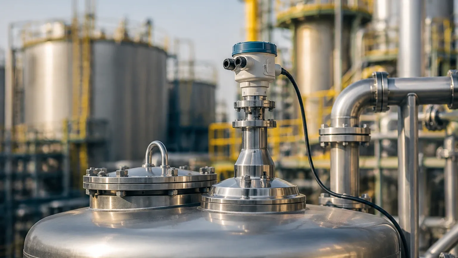
For B2B buyers and procurement managers sourcing Radar Level Meters for global projects, the following technical specifications must be confirmed with the manufacturer:
1. Certification and Compliance: Does the device meet local hazardous area requirements? Look for ATEX (Europe), IECEx (International), or CSA/UL (North America) certifications for explosive atmospheres.
2. Output Protocols: Ensure compatibility with the existing control system. Standard options include 4-20mA with HART, Modbus RTU (RS485), or Foundation Fieldbus.
3. Material Compatibility: Verify that the wetted parts (the parts of the antenna exposed to the process) are compatible with the chemicals in the tank. SS316L is standard, but aggressive acids may require PTFE or Hastelloy coatings.
4. Measurement Range: Confirm the maximum range. While some radars can measure up to 120 meters (393 feet), accuracy often decreases at the extreme ends of the range.
5. Process Connection: Specify the flange size (DN or ANSI) or thread type (G or NPT) to ensure a seamless mechanical fit during installation.
6. Frequently Asked Questions (FAQ)
Q: Can a non-contact radar measure through a plastic tank wall?
A: Yes. Since plastic and fiberglass are non-conductive and have low dielectric constants, radar signals can pass through them. This allows for measurement without cutting a hole in the tank, provided the material inside has a significantly higher dielectric constant than the tank wall.
Q: How does dust affect 80 GHz radar?
A: While 80 GHz radar has a shorter wavelength, modern high-frequency sensors are designed with high sensitivity. In most dust applications (like grain or plastic pellets), the narrow beam allows the signal to find a path through the dust cloud more effectively than wider-beam lower-frequency units.
Q: Is calibration required for radar level transmitters?
A: Unlike hydrostatic transmitters that depend on density, radar measures distance. Therefore, it does not require recalibration if the fluid density changes. However, a "zero-point" and "span" setup is required during initial commissioning to define the tank bottom and the 100% fill level.
Q: What is the difference between "Non-Contact" and "Guided Wave" radar?
A: Non-contact radar sends waves through the air. Guided Wave Radar (GWR) sends the signal down a physical probe or cable. GWR is better for low-dielectric liquids and foam, while non-contact radar is preferred for corrosive, sticky, or hygienic applications where touching the media is undesirable.
Conclusion
The radar level transmitter non contact represents the pinnacle of modern level sensing technology. By understanding the nuances of frequency selection, the impact of dielectric constants, and the necessity of precise installation, engineers can implement a measurement solution that requires minimal maintenance and provides years of accurate data. Whether managing water treatment facilities or complex chemical reactors, selecting the appropriate Radar Level Meters is a critical step toward achieving operational excellence in industrial automation.