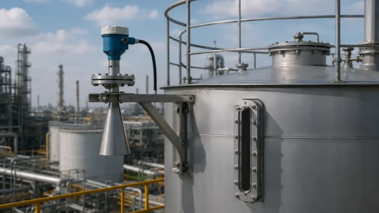
Radar Level Controller
Radar Level Controller: A Technical Guide to Industrial Implementation
In the landscape of industrial process automation, the ability to monitor and manage liquid or solid levels with high precision is fundamental to operational safety and efficiency. A radar level controller serves as the intelligence center of this process, integrating non-contact sensing technology with sophisticated signal processing to provide real-time data and automated control logic. Unlike traditional mechanical floats or pressure-based systems, radar-based solutions offer a maintenance-free approach that remains unaffected by changes in density, temperature, or pressure.
Selecting the appropriate Radar Level Meters requires a deep understanding of microwave physics, vessel geometry, and the chemical properties of the media being measured. This guide explores the engineering principles, selection criteria, and installation constraints necessary for successful deployment in B2B industrial environments.
1. Measurement Principles of Radar Technology
Before implementing a radar level controller, it is essential to understand how the underlying sensor gathers data. Industrial radar systems primarily utilize two methods: Pulse Radar and Frequency Modulated Continuous Wave (FMCW).
Pulse Radar (Time-of-Flight)
Pulse radar instruments emit a series of short-duration microwave pulses toward the material surface. These pulses travel at the speed of light, reflect off the media, and return to the sensor's antenna. The controller measures the "Time-of-Flight" (ToF) between emission and reception. Since the speed of light is constant, the distance is calculated using the formula:
Distance = (Speed of Light × Travel Time) / 2
Pulse radar is often favored for its lower power consumption and suitability for simple liquid level applications where extreme precision (sub-millimeter) is not the primary requirement.
FMCW (Frequency Modulated Continuous Wave)
FMCW radar technology is the gold standard for high-accuracy industrial applications. Instead of pulses, the transmitter emits a continuous signal with a constantly changing frequency (a frequency sweep). When the reflected signal is received, it is compared to the signal being emitted at that exact moment. The difference in frequency (the "beat frequency") is directly proportional to the distance.
Modern FMCW systems operating at 80GHz provide a much narrower beam angle and higher bandwidth than older 6GHz or 26GHz models, allowing the radar level controller to distinguish between the true material level and internal tank obstructions like agitators or heating coils.
2. The Role of the Radar Level Controller
While the radar head acts as the sensor, the "controller" aspect refers to the integrated electronics and software that translate raw distance data into actionable industrial signals. A robust radar level controller performs several critical functions:
* Signal Processing & Filtering: It uses algorithms to filter out "false echoes" caused by tank walls, ladders, or surface turbulence.
* Linearization: In non-cylindrical tanks (such as horizontal tanks with dish ends), the controller converts the measured level into a volume reading (liters, cubic meters, or gallons).
* Output Management: It provides standardized outputs, typically 4-20mA with HART protocol, Modbus RS485, or Profibus, allowing integration into a PLC (Programmable Logic Controller) or SCADA system.
* Relay Logic: Many controllers include onboard relays to trigger high-level alarms or start/stop pumps directly, providing a redundant safety layer independent of the primary control system.
3. Technical Selection Criteria
Selecting the right equipment involves balancing the physical properties of the medium against the environmental conditions of the vessel. The following table provides a comparison of common radar frequencies used in industrial level measurement.
Table 1: Comparison of Radar Technologies
| Feature | 26GHz Pulse/FMCW | 80GHz FMCW |
| :— | :— | :— |
| Beam Angle | 8° to 20° | 3° to 8° |
| Measurement Accuracy | ±3mm to ±5mm | ±1mm to ±2mm |
| Max Measurement Range | 30m to 70m | Up to 120m |
| Suitability for Dust | Moderate | Excellent |
| Small Vessel Performance | Limited by beam width | Excellent (Narrow beam) |
| Dielectric Sensitivity | High | Very High |
Dielectric Constant (εr)
The Dielectric Constant of the medium is the most critical factor in radar selection. It determines how much energy is reflected back to the sensor.
* High εr (>10): Water-based liquids provide strong reflections and are easy to measure.
* Low εr (1.4 to 4): Hydrocarbons, oils, and some plastic pellets reflect very little energy. These require high-sensitivity radar level controllers or Guided Wave Radar (GWR) to ensure signal stability.
4. Installation Considerations and Constraints
Even the most advanced radar level controller will fail if installed incorrectly. Engineers must adhere to strict geometric constraints to avoid signal interference.
Nozzle Placement and Height
The radar antenna should not be installed in the center of a tank, as this can lead to multiple reflections (parabolic effect) that confuse the controller. Conversely, it should not be placed too close to the tank wall, where the beam might interact with weld seams or buildup. A general rule is to install the sensor at 1/4 to 1/6 of the tank diameter from the wall.
Beam Angle and Obstructions
The "beam angle" defines the area where the radar energy is concentrated. Any physical object within this cone—such as a ladder, a pipe, or an agitator—will create an echo. While modern controllers feature "False Signal Suppression" to ignore these echoes, it is best practice to provide a clear line of sight to the product surface. Narrower beam angles (80GHz) are significantly easier to install in crowded vessels.
Dead Zones (Blocking Distance)
Every radar sensor has a "dead zone" or "upper blocking distance" directly below the antenna (typically 50mm to 200mm). The radar level controller cannot accurately measure level within this zone. If the tank must be filled to the very top, a nozzle extension or a specific antenna design may be required to move the dead zone outside the working range of the vessel.
5. Application Risks and Limitations
While radar is highly versatile, certain process conditions can attenuate the signal or create measurement errors.
1. Heavy Foam: Dense, thick foam can absorb microwave signals entirely, preventing them from reaching the liquid surface. In cases of light foam, 26GHz radar often performs better as it can penetrate the surface more effectively than higher frequencies.
2. Heavy Dust and Condensation: While 80GHz radar is excellent for solids, extreme dust during pneumatic filling can temporarily attenuate the signal. Similarly, heavy condensation on the antenna lens can cause signal scattering. Choosing an antenna with a PTFE (Teflon) cover or a purging connection can mitigate these risks.
3. Vortex and Turbulence: Rapidly mixing liquids create a vortex or turbulent surface, which scatters the radar signal. The controller's software must be configured with a higher "damping" value to average out these fluctuations and provide a steady output.
6. Buyer’s Checklist: Information Required for Specification
When sourcing a radar level controller from international manufacturers, providing a complete data sheet ensures the equipment is fit for purpose. Ensure you confirm the following parameters:
* Medium Properties: Name of the medium, dielectric constant (if known), and whether it is corrosive or abrasive.
* Process Temperature & Pressure: Standard operating levels and maximum possible excursions. High-pressure flanges or high-temperature ceramic buffers may be necessary.
* Vessel Dimensions: Total height, diameter, and the height of the mounting nozzle.
* Connection Type: Threaded (G or NPT) or Flanged (ANSI, DIN, or JIS standards).
* Output Requirements: Is a simple 4-20mA signal sufficient, or is digital communication (Modbus/HART) required for remote diagnostics?
7. Frequently Asked Questions (FAQ)
Q: Can a radar level controller measure through a plastic tank wall?
A: Yes. Since microwaves can penetrate non-conductive materials like plastic or glass, radar sensors can often be mounted above a plastic IBC or tank to measure the level without making contact with the liquid.
Q: How does a radar level controller handle internal agitators?
A: Most controllers include a "mapping" or "learning" function. You empty the tank, and the controller scans the interior, recording the location of fixed obstructions. It then ignores these static echoes during normal operation.
Q: Is radar better than ultrasonic for level measurement?
A: In most industrial B2B applications, radar is superior. It is not affected by air temperature, vacuum, or vapor, all of which significantly impact the speed of sound and, therefore, the accuracy of ultrasonic sensors.
Conclusion
The integration of a radar level controller into an industrial process provides a level of reliability and precision that is difficult to match with other technologies. By understanding the nuances of frequency selection, dielectric properties, and installation geometry, engineers can implement a solution that reduces downtime and enhances safety. For complex environments involving narrow tanks or high-precision requirements, modern 80GHz Radar Level Meters offer the most robust path forward, ensuring that level data remains accurate even in the most challenging process conditions.