Heat Flow Sensor
Heat Flow Sensor
In industrial process control and thermal management, understanding the movement of energy is as critical as monitoring pressure, flow, or liquid levels. A heat flow sensor (HFS), also known as a heat flux transducer, is a specialized instrument designed to measure the rate of heat energy transfer through a surface. Unlike a thermometer, which measures the thermal state (temperature) of an object, a heat flow sensor quantifies the dynamic exchange of energy in Watts per square meter (W/m²).
For engineers managing complex industrial systems, heat flow data provides insights into insulation efficiency, chemical reaction rates, and the structural integrity of high-temperature vessels. This guide explores the principles, selection criteria, and practical applications of heat flow sensors within the broader context of industrial instrumentation.
Measurement Principles of Heat Flow Sensors
To select the correct instrument, it is essential to understand the physics governing heat flux measurement. Most industrial heat flow sensors operate based on the principle of thermal resistance and the Seebeck effect.
The Differential Temperature Method
At its core, a heat flow sensor consists of a thin layer of material with a precisely known thermal resistance ($R_{th}$). When heat passes through this material, a temperature gradient ($ΔT$) is established between the two sides. According to Fourier’s Law of Heat Conduction, the heat flux ($Φ$) is proportional to this temperature difference:
$$Φ =
rac{ΔT}{R_{th}}$$
The Thermopile Construction
To convert this temperature difference into a measurable electrical signal, manufacturers use a thermopile. A thermopile is a series of thermocouples connected in electrical series but thermal parallel. Each thermocouple junction generates a small voltage (the Seebeck effect) in response to the temperature gradient. By layering hundreds of these junctions across the thermal resistance layer, the sensor produces a millivolt (mV) output that is directly proportional to the heat flux. This passive design allows many heat flow sensors to operate without external power, making them highly reliable in remote or hazardous industrial environments.
Core Technologies and Sensor Designs
Heat flow sensors are categorized by their physical construction and the specific environment they are designed to monitor.
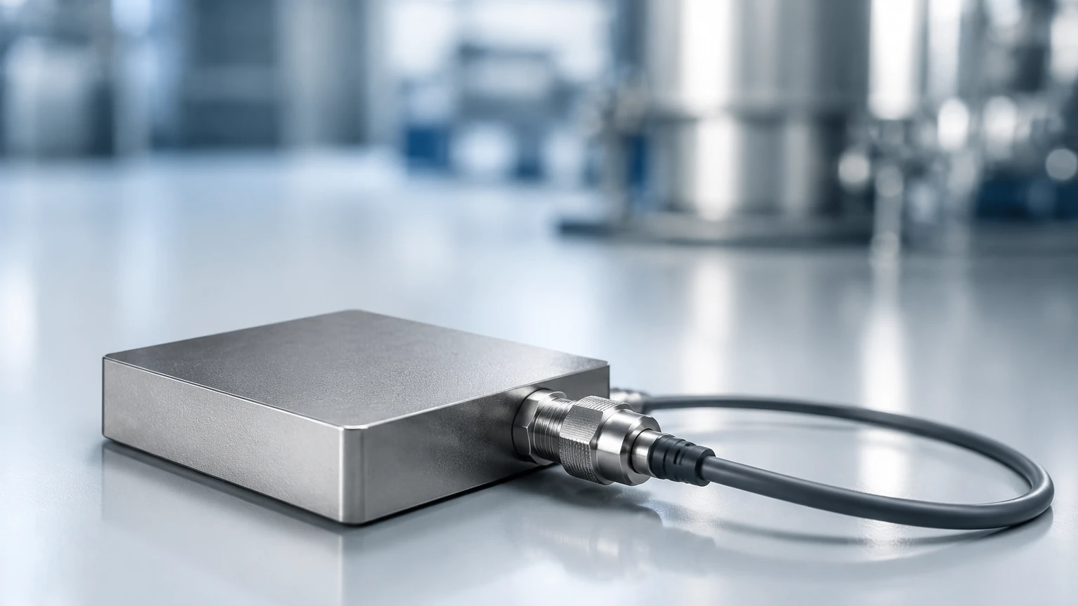
1. Plate-Type Sensors: These are rigid sensors, often encapsulated in epoxy or ceramic. They are used for flat surfaces like furnace walls, building envelopes, or soil heat flux measurement. They offer high durability and stable calibration constants.
2. Thin-Film Flexible Sensors: Constructed on polyimide or other flexible substrates, these sensors are designed to wrap around pipes or curved vessel walls. They are typically less than 0.5 mm thick, minimizing the disturbance to the original heat flow path.
3. Water-Cooled Heat Flux Meters: Used in extreme environments like combustion chambers or aerospace testing, these sensors use internal water circulation to protect the sensing element from melting while measuring high-intensity radiant heat.
Industrial Selection Criteria
Choosing a heat flow sensor requires balancing sensitivity with environmental resilience. Engineers should evaluate the following parameters:
* Sensitivity ($S$): Measured in microvolts per Watt per square meter ($μV / (W/m²)$). A higher sensitivity is required for low-heat-flux applications, such as monitoring heat loss through high-performance insulation.
* Temperature Range: Sensors must withstand the process temperature. Standard sensors may handle up to 150°C, while specialized ceramic versions can exceed 1000°C.
* Thermal Conductivity Matching: To avoid "measurement bypass," the thermal conductivity of the sensor should ideally match the conductivity of the material it is mounted on. If the sensor is significantly more or less conductive than the surface, it will distort the local heat flow, leading to inaccurate readings.
* Response Time: Defined as the time required for the sensor to reach 95% of its final value. Thin-film sensors typically offer faster response times (milliseconds) compared to thicker plate-type sensors.
Practical Selection Table
| Application | Recommended Sensor Type | Typical Heat Flux Range | Key Consideration |
| :— | :— | :— | :— |
| Building Insulation | High-sensitivity Plate | 0 – 100 W/m² | High $μV$ output for low flux |
| Industrial Furnaces | Ceramic Plate | 5 – 50 kW/m² | High temperature resistance |
| Pipe Monitoring | Thin-Film Flexible | 10 – 500 W/m² | Flexibility for curvature |
| Chemical Reactors | Encapsulated Plate | 100 – 2000 W/m² | Chemical compatibility |
| Cryogenic Tanks | Cryo-rated Thin Film | < 10 W/m² | Low-temperature calibration |
Installation and Mounting Guidelines
The accuracy of a heat flow sensor is heavily dependent on the quality of its installation. Even the most precise sensor will yield false data if there is a thermal gap between the sensor and the target surface.
Surface Preparation
The mounting surface must be clean, flat, and free of oxidation. For industrial applications, a thermal interface material (TIM), such as thermal grease or a conductive adhesive, should be used to eliminate air pockets. Air has extremely low thermal conductivity and acts as an insulator, which would cause the sensor to underreport the actual heat flux.
Guarding and Insulation
When a sensor is mounted on a surface, it creates a small "bump" in thermal resistance. To mitigate this, engineers often use "guarding"—surrounding the sensor with a material of the same thickness and thermal properties. Furthermore, if the sensor is measuring heat loss to the ambient air, it should not be covered by thick insulation unless the goal is to measure the flux *through* that insulation.
Wiring and Signal Conditioning
Since the output is often in the millivolt range, shielded cabling is mandatory to prevent electromagnetic interference (EMI) from high-power industrial equipment. Signal conditioners or data loggers with high-resolution analog-to-digital converters (at least 16-bit) are recommended to capture subtle changes in energy flow.
Relationship with Level Measurement and Process Control
While heat flow sensors focus on energy transfer, they are frequently used in tandem with other process instruments, such as level meters. In many industrial scenarios, thermal data provides a secondary layer of validation for level sensing.
For example, in large oil or chemical storage tanks, a heat flow sensor can detect the liquid-gas interface because liquids and gases have vastly different heat transfer coefficients. If a primary radar level meter reports a specific level, heat flux data can confirm this by identifying the point where thermal dissipation changes.
In high-temperature applications, such as molten metal or glass production, monitoring the heat flux through the vessel walls is essential for safety. Excessive heat flow can indicate that the refractory lining has thinned, posing a risk of a breakout. Integrating these readings with reliable level data ensures that the volume of the hazardous material is always accounted for. For engineers looking to integrate comprehensive monitoring systems, reviewing diverse product options and application support on the Main Page can help in selecting the right combination of level and thermal sensors.
Limitations and Potential Error Sources
No measurement technology is without limitations. When deploying heat flow sensors, be aware of the following risks:
* Thermal Bridging: Fasteners or mounting brackets made of metal can act as thermal bridges, drawing heat away from the sensor and skewing the data.
* Calibration Drift: Over time, exposure to extreme temperatures or corrosive atmospheres can degrade the thermopile junctions. Periodic recalibration against a known heat source is necessary for long-term accuracy.
* Convection and Radiation Interference: Some sensors are sensitive to both conductive and radiative heat. If you only wish to measure conduction, the sensor may need a low-emissivity coating to reflect radiant energy.
* Sensor Thickness: In thin materials (like a metal sheet), the sensor's own thermal resistance might be higher than the material it is measuring, which significantly alters the heat flow path (the "self-insulation" effect).
Frequently Asked Questions (FAQs)
Q: Can a heat flow sensor measure temperature?
A: Most heat flow sensors include an integrated thermocouple or RTD (Resistance Temperature Detector) to measure the absolute temperature of the surface, but the primary function of the HFS is to measure the energy *movement*, not the temperature itself.
Q: How is a heat flow sensor calibrated?
A: Calibration is typically performed using a Guarded Hot Plate (GHP) or a heat flow meter apparatus according to standards like ASTM C177 or ISO 8302. A known amount of energy is passed through the sensor, and the voltage output is recorded to determine the sensitivity constant.
Q: Is it possible to measure heat flow without contact?
A: Direct heat flow sensors require physical contact to measure conduction. However, infrared (IR) radiometers can measure radiative heat flux from a distance. For most industrial process applications involving solids and liquids, contact-based HFS is the standard.
Q: How do I choose between a heat flow sensor and a temperature sensor?
A: Use a temperature sensor if you need to know if a substance is at the correct thermal state (e.g., "Is the water at 80°C?"). Use a heat flow sensor if you need to know how much energy is being lost, gained, or transferred (e.g., "How much energy is escaping through this boiler wall?").
By understanding these principles and selection criteria, process engineers can better manage the thermal dynamics of their operations, leading to improved energy efficiency, enhanced safety, and more robust process control. Whether used as a standalone tool or as a complement to level measurement systems, the heat flow sensor remains a vital component of the modern industrial toolkit.