Clamp on Gas Flow Meter
Clamp on Gas Flow Meter
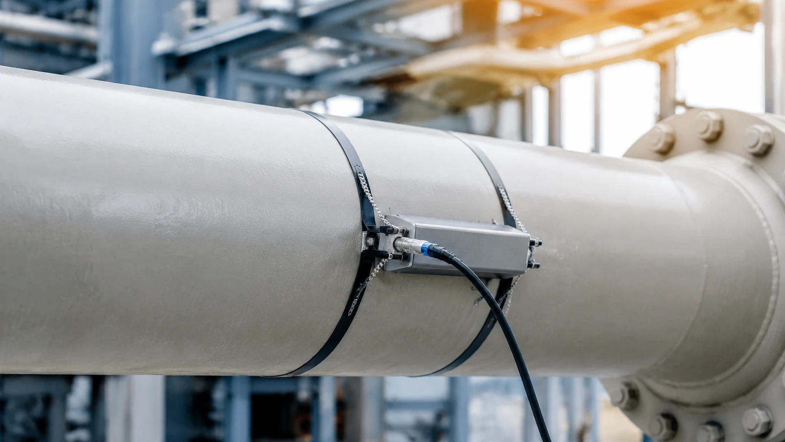
In the landscape of industrial process control, the ability to measure flow without interrupting production or compromising the integrity of a piping system is a significant advantage. The clamp on gas flow meter represents a sophisticated application of ultrasonic technology, designed to provide accurate flow data from the outside of a pipe. Unlike traditional inline flow meters that require cutting pipes and installing flanges, clamp-on systems utilize external transducers to transmit and receive signals through the pipe wall and the gas medium.
This guide explores the engineering principles, selection criteria, and practical installation requirements for clamp on gas flow meters, providing a technical reference for engineers and plant managers seeking non-invasive measurement solutions.
Measurement Principles of Clamp on Gas Flow Meters
The majority of clamp on gas flow meters operate on the Transit-Time Ultrasonic principle. This method relies on the fact that sound waves traveling with the flow of a gas move faster than those traveling against it.
Transit-Time Difference
Two ultrasonic transducers are mounted on the exterior of the pipe. These transducers function as both transmitters and receivers. They emit ultrasonic pulses that travel through the pipe wall, across the gas stream, and through the opposite pipe wall to be received by the second transducer.
1. Upstream Transmission: The signal traveling against the flow takes longer ($t_{up}$).
2. Downstream Transmission: The signal traveling with the flow takes less time ($t_{down}$).
The difference in transit time ($Δt$) is directly proportional to the velocity of the gas within the pipe. By integrating this velocity with the cross-sectional area of the pipe (and accounting for the gas's compressibility and temperature), the meter calculates the volumetric and mass flow rates.
The Challenge of Gas vs. Liquid
Measuring gas with clamp-on technology is significantly more complex than measuring liquids. This is primarily due to acoustic impedance. Gases have much lower density than liquids, which creates a massive impedance mismatch between the metal pipe wall and the gas inside. This mismatch causes a large portion of the ultrasonic energy to reflect off the inner pipe wall rather than entering the gas. Advanced signal processing and high-gain transducers are required to extract a usable signal from the small amount of energy that successfully traverses the gas medium.
Key Evaluation and Selection Criteria
Selecting a clamp on gas flow meter requires a thorough understanding of the process conditions. Because the signal must pass through the pipe wall, the physical properties of both the pipe and the gas are critical.
1. Minimum Operating Pressure
For most ultrasonic clamp-on meters, gas pressure is the most critical factor. Higher pressure increases the density of the gas, which improves the acoustic coupling between the pipe wall and the gas.
* Standard Systems: Typically require a minimum of 5 to 10 bar (72 to 145 psi) for steel pipes.
* Low-Pressure Systems: Specialized transducers may allow measurement at lower pressures, but accuracy often decreases as pressure approaches atmospheric levels.
2. Pipe Material and Condition
The pipe must be a sonically conductive material such as carbon steel, stainless steel, or certain plastics. Heavily corroded pipes, or those with internal liners (like cement or thick rubber), can attenuate the signal to the point where measurement is impossible. The exterior surface must be ground smooth to ensure the transducers make flush contact.
3. Gas Composition
The meter must be programmed with the specific properties of the gas, including its molecular weight and adiabatic index. Mixtures like natural gas require detailed analysis to ensure the speed of sound calculations remain accurate. If the gas contains high levels of moisture or entrained liquids (wet gas), the ultrasonic signal can be scattered, leading to measurement errors.
4. Flow Velocity Range
Clamp-on meters are excellent for measuring high-velocity gas flows, often up to 30 m/s or higher. However, they may struggle with extremely low velocities where the time difference ($Δt$) becomes too small to distinguish from electronic noise.
Practical Selection Table
| Feature | Requirement / Specification |
| :— | :— |
| Pipe Sizes | 25 mm to 5000 mm (1" to 200") |
| Minimum Pressure | ≥ 5 bar (for metal pipes) |
| Accuracy | ±1.0% to ±3.0% of reading |
| Repeatability | 0.2% to 0.5% |
| Gas Types | Natural gas, Compressed air, Nitrogen, Oxygen, CO2 |
| Temperature Range | -40°C to +250°C (Standard) |
| Output Options | 4-20mA, Modbus RTU, HART, Pulse |
For comprehensive instrumentation needs beyond flow, such as liquid level monitoring in high-pressure tanks, engineers often consult specialized manufacturers like Welk to ensure all process variables are accurately tracked.
Installation Considerations and Best Practices
The performance of a clamp on gas flow meter is heavily dependent on the quality of the installation. Unlike inline meters, the "sensor" is essentially the pipe itself, meaning the installer must be meticulous.
Straight Pipe Requirements
To ensure a stable and predictable flow profile, the transducers must be placed on a straight section of pipe.
* Upstream: Minimum 10D to 20D (where D is the pipe diameter) after elbows, valves, or reducers.
* Downstream: Minimum 5D before any disturbances.
If these distances cannot be met, the meter's accuracy will likely deviate from the manufacturer's specifications.
Transducer Mounting Configurations
There are two primary mounting modes for gas applications:
1. Reflect Mode (V-Mount): The signal bounces off the opposite wall once. This is common for smaller pipes where the signal path is short.
2. Direct Mode (Z-Mount): Transducers are mounted on opposite sides of the pipe. This is the preferred method for gas because it minimizes the distance the signal travels through the gas, reducing attenuation.
Coupling Agents
An acoustic coupling grease or pad must be used between the transducer face and the pipe wall. This eliminates air gaps that would otherwise block the ultrasonic signal. For permanent installations, solid coupling pads or high-temperature silicone are often used to prevent the couplant from drying out over time.
Common Risks and Limitations
While highly versatile, clamp-on technology is not a universal solution for every gas application. Engineers should be aware of the following risks:
* Pipe Wall Thickness: Extremely thick-walled pipes (e.g., Schedule 160) require more energy to penetrate. If the wall is too thick relative to the pipe diameter, the signal-to-noise ratio may be too low.
* Signal Short-Circuiting: In some cases, the ultrasonic signal travels around the circumference of the pipe wall (structural noise) faster than it travels through the gas. Advanced meters use "anti-noise" algorithms to filter this out, but it remains a challenge for thin-walled metal pipes.
* Ambient Noise: High-frequency noise from nearby pressure-reducing valves or compressors can interfere with the ultrasonic frequency of the transducers (typically 0.5 MHz to 2 MHz).
* Calibration Verification: Since the meter is not in contact with the fluid, verifying its calibration in the field can be difficult. It is often recommended to use a master meter or perform a "zero-flow" check if the process can be temporarily stopped.
Comparison with Other Flow Technologies
| Technology | Non-Invasive? | Pressure Drop? | Maintenance | Suitability for Gas |
| :— | :— | :— | :— | :— |
| Clamp-on Ultrasonic | Yes | Zero | Low | High (if P > 5 bar) |
| Thermal Mass | No | Negligible | Moderate | Excellent for low flow |
| Vortex | No | Low to Med | Low | Good for high velocity |
| Orifice Plate | No | High | High | Traditional standard |
Frequently Asked Questions (FAQ)
Q: Can a clamp on gas flow meter measure steam?
A: Generally, no. Steam is a challenging medium due to high temperatures and the presence of condensate droplets which scatter ultrasonic signals. While some specialized high-temperature systems exist, they are rarely used for steam compared to vortex or differential pressure meters.
Q: Does pipe material affect the accuracy?
A: Yes. The meter must know the exact sonic velocity of the pipe material to calculate the refraction angle of the signal. Materials like cast iron, which may have internal voids or inconsistent density, are more difficult to measure than extruded stainless steel.
Q: What happens if the gas composition changes?
A: If the gas composition changes significantly (e.g., a shift in the methane/ethane ratio in natural gas), the programmed speed of sound in the meter will be incorrect, leading to a linear offset in flow measurement. Modern meters allow for real-time compensation if an external gas analyzer or pressure/temperature sensor is integrated.
Q: Is it possible to measure gas at atmospheric pressure?
A: It is extremely difficult for metal pipes due to the impedance mismatch. Some success has been found with plastic pipes at low pressure, but for metal pipes, a minimum of 5 bar is typically the industry standard for reliable operation.
Conclusion
The clamp on gas flow meter is a powerful tool for industrial energy management, leak detection, and process monitoring. By eliminating the need for pipe modifications, it reduces installation costs and prevents potential leak points. However, successful implementation requires careful attention to pipe condition, gas pressure, and correct transducer alignment. For facilities looking to integrate comprehensive measurement strategies, including level and flow, visiting the Main Page of a professional instrumentation provider can provide further insights into matching the right technology to the specific industrial application.