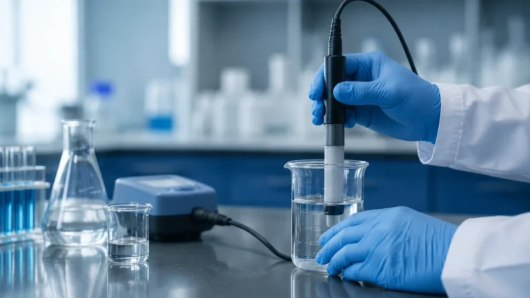
Unit of Measure for Conductivity
Unit of Measure for Conductivity
In industrial process control and water treatment, understanding the electrical properties of a liquid is essential for both quality monitoring and level detection. Electrical conductivity is a measure of a solution's ability to conduct an electric current. This ability is directly related to the concentration of ions—such as salts, acids, or bases—dissolved in the liquid. For engineers and technicians, selecting the correct unit of measure for conductivity is the first step in ensuring accurate sensor calibration and reliable process data.
Conductivity measurement is not only used to determine the purity of water but also serves as a fundamental principle for certain types of level instrumentation. By identifying the conductivity of a medium, operators can implement conductive level switches that detect the presence or absence of liquid at specific points in a tank or vessel. As a professional manufacturer, Welk provides a range of measurement solutions that rely on these electrochemical principles to deliver precision in industrial automation.
Understanding Electrical Conductivity in Industrial Processes
Electrical conductivity, often represented by the Greek letter sigma (σ) or kappa (κ), occurs when ions in a solution migrate in response to an electrical field. In aqueous solutions, the current is carried by dissolved electrolytes. The more ions present, the higher the conductivity of the liquid. Conversely, pure water, which contains very few ions, acts as an insulator.
In a B2B context, monitoring conductivity is vital for several reasons:
1. Water Quality: In power plants and pharmaceutical manufacturing, ultrapure water must have extremely low conductivity to prevent equipment corrosion or product contamination.
2. Chemical Concentration: Many industrial processes involve mixing acids or alkalis with water. Because conductivity increases with ion concentration, it can be used to infer the strength of a chemical solution.
3. Interface Detection: In systems where oil (non-conductive) and water (conductive) coexist, conductivity sensors can identify the boundary between the two liquids.
The Standard Unit of Measure for Conductivity
The International System of Units (SI) defines the unit of measure for conductivity as Siemens per meter (S/m). However, because many industrial fluids have relatively low conductivity, this unit is often scaled down to more practical dimensions for field use.
Microsiemens and Millisiemens
In most water treatment and general industrial applications, the most common unit of measure for conductivity is the microsiemens per centimeter (µS/cm). For more concentrated solutions, such as seawater or concentrated acids, the millisiemens per centimeter (mS/cm) is preferred.
* 1 S/m = 10 mS/cm
* 1 mS/cm = 1,000 µS/cm
* 1 S/m = 10,000 µS/cm
Historically, the unit of conductivity was the "mho" (ohm spelled backward), representing the reciprocal of resistance. One mho is equivalent to one Siemens. While the term mho is still occasionally found in legacy documentation, modern engineering standards exclusively use the Siemens.
The Relationship Between Conductivity and Resistivity
In specific high-purity applications, such as semiconductor manufacturing or boiler feedwater monitoring, it is more common to discuss the liquid's "resistivity" rather than its conductivity. Resistivity is the mathematical reciprocal of conductivity.
The unit of measure for resistivity is the Ohm-centimeter (Ω·cm). For ultrapure water, the theoretical limit of resistivity is 18.2 MΩ·cm at 25°C. To convert between the two:
$$\text{Resistivity (M\Omega\cdot cm)} = \frac{1}{\text{Conductivity (\mu S/cm)}}$$
For example, a conductivity of 0.055 µS/cm corresponds to a resistivity of approximately 18.18 MΩ·cm. Understanding this inverse relationship is critical when configuring transmitters that may offer both display options.
Measurement Principles: Contacting vs. Inductive
To accurately determine the conductivity of a fluid, industrial sensors employ one of two primary measurement principles. The choice between them depends on the expected conductivity range and the chemical nature of the fluid.
Contacting Conductivity Sensors
Contacting sensors utilize electrodes (usually two or four) that come into direct contact with the process liquid. An AC voltage is applied between the electrodes, and the resulting current is measured.
* Two-Electrode Sensors: Best suited for low-conductivity applications like pure water. They are sensitive to electrode fouling and polarization at high conductivities.
* Four-Electrode Sensors: These use two drive electrodes and two sensing electrodes to eliminate the effects of polarization and cable resistance, making them suitable for a wider range of conductivities.
Inductive (Toroidal) Conductivity Sensors
Inductive sensors use two wire-wound coils encased in a plastic or ceramic housing. One coil induces an electric current in the surrounding liquid, and the second coil measures the strength of that current. Because the sensor does not have exposed metal electrodes, it is immune to fouling, coating, and corrosion. This makes it the preferred choice for wastewater, heavy chemicals, and slurries where the unit of measure for conductivity might reach several hundred mS/cm.
The Role of the Cell Constant (K)
The raw measurement taken by a sensor is conductance (measured in Siemens), which depends on the geometry of the sensor. To convert conductance into the standardized unit of measure for conductivity (S/cm), a "Cell Constant" (K) must be applied.
The Cell Constant is defined as the ratio of the distance (L) between the electrodes to the cross-sectional area (A) of the liquid through which the current passes:
$$K = L / A$$
* Low Cell Constants (e.g., K=0.1): Used for low-conductivity liquids (pure water). The electrodes are placed close together or have a large surface area to produce a measurable signal.
* High Cell Constants (e.g., K=10): Used for high-conductivity liquids (brine, acids). The electrodes are smaller or further apart to prevent the current from becoming too high for the electronics to process accurately.
Conductivity in Level Detection and Control
Beyond monitoring fluid quality, conductivity is a robust method for point-level detection. Conductive level switches operate by using the liquid itself as a conductor to close an electrical circuit between a probe and the tank wall (or a reference probe).
When the conductive liquid reaches the probe tip, a small current flows, signaling the controller that the high-level limit has been reached. This technology is highly reliable for water-based liquids but cannot be used for non-conductive substances like oils or hydrocarbons. When selecting a level instrument, engineers should consult the Main Page of a specialized manufacturer like Welk to compare conductive switches against other technologies like ultrasonic or radar level meters, which are independent of the fluid's electrical properties.

Fluid Conductivity Reference Table
The following table provides typical conductivity ranges for common industrial fluids. This data helps in selecting the appropriate sensor type and cell constant.
| Fluid Type | Typical Conductivity Range | Preferred Unit | Sensor Type |
| :— | :— | :— | :— |
| Ultrapure Water | 0.055 µS/cm | µS/cm | Contacting (K=0.01 or 0.1) |
| Distilled Water | 0.5 – 5.0 µS/cm | µS/cm | Contacting (K=0.1) |
| Boiler Feedwater | 1.0 – 50 µS/cm | µS/cm | Contacting (K=0.1 or 1.0) |
| Drinking Water | 50 – 800 µS/cm | µS/cm | Contacting (K=1.0) |
| Wastewater | 500 – 5,000 µS/cm | µS/cm | Inductive or Contacting |
| Seawater | 50,000 µS/cm (50 mS/cm) | mS/cm | Inductive |
| 10% Sulfuric Acid | 430,000 µS/cm (430 mS/cm) | mS/cm | Inductive |
Engineering Considerations for Installation
To ensure that the measured unit of measure for conductivity remains accurate over time, several installation factors must be addressed:
1. Temperature Compensation: Conductivity is highly temperature-dependent. For most aqueous solutions, conductivity increases by approximately 2% per degree Celsius. Modern transmitters use integrated temperature sensors (like Pt100 or Pt1000) to normalize the reading to a reference temperature, usually 25°C.
2. Probe Placement: The sensor must be fully submerged in the liquid at all times. In pipe installations, the sensor should be placed in a vertical run with an upward flow to prevent air pockets from forming around the electrodes.
3. Grounding: In plastic tanks or lined pipes, a grounding electrode or reference probe is necessary to provide a return path for the electrical signal in conductive level applications.
4. Cable Interference: Conductivity signals, especially at low levels, are susceptible to electromagnetic interference (EMI). Shielded cables should be used, and the distance between the sensor and the transmitter should be minimized unless a digital protocol (like Modbus or IO-Link) is employed.
Limitations and Maintenance Requirements
While conductivity measurement is a mature and reliable technology, it has specific limitations that can affect the accuracy of the reported unit of measure for conductivity.
* Fouling and Scaling: In contacting sensors, the buildup of calcium, oil, or biological growth on the electrodes adds resistance, leading to falsely low conductivity readings. Regular cleaning with appropriate solvents or dilute acids is required.
* Polarization: Using a DC voltage for measurement would cause ions to accumulate at the electrodes, creating a "back-EMF" that opposes the current. Industrial sensors use AC voltage to prevent this, but at very high conductivities, even AC sensors can experience polarization errors.
* Non-Conductive Media: Conductivity-based level switches will fail to detect liquids with high resistance. For such applications, hydrostatic pressure transmitters or radar level meters are more appropriate alternatives.
Frequently Asked Questions (FAQs)
Q: What is the difference between Conductivity and Total Dissolved Solids (TDS)?
A: Conductivity measures the ability of a solution to pass current, while TDS measures the total mass of dissolved solids in a given volume of water (usually in mg/L or ppm). Since most dissolved solids are ionic, conductivity can be used to estimate TDS by applying a conversion factor (typically 0.5 to 0.7), though this factor varies depending on the specific ions present.
Q: Why is the unit of measure for conductivity expressed "per centimeter" or "per meter"?
A: Conductivity is an intrinsic property of the material. By including a distance unit (cm or m), the measurement becomes independent of the specific size of the sample, allowing for a standardized comparison between different fluids regardless of the sensor geometry.
Q: How often should a conductivity sensor be calibrated?
A: In stable, clean water applications, calibration may only be needed once or twice a year. In harsh chemical processes or wastewater, monthly or even weekly verification against a known standard solution is recommended to account for electrode wear or fouling.
Conclusion
Selecting and understanding the correct unit of measure for conductivity is vital for maintaining process efficiency and safety in B2B industrial environments. Whether monitoring the purity of boiler feedwater in µS/cm or managing the concentration of industrial cleaners in mS/cm, the accuracy of these measurements depends on proper sensor selection, cell constant application, and temperature compensation. For organizations seeking integrated level and process measurement hardware, reviewing the technical capabilities of various sensors on the Main Page of an established manufacturer ensures that the chosen solution aligns with the specific conductivity and chemical requirements of the application.