Insertion Mag Flow Meter
Insertion Mag Flow Meter
In the landscape of industrial flow measurement, the insertion mag flow meter represents a versatile and cost-effective solution for monitoring conductive fluids in large-diameter piping systems. Unlike traditional full-bore electromagnetic flow meters that require a section of the pipe to be removed and replaced by the meter body, insertion models are designed to be installed through a single point of entry. This design offers significant advantages in terms of installation labor, hardware costs, and process continuity.
For engineers and facility managers overseeing water treatment, chemical processing, or industrial automation, understanding the technical nuances of the insertion mag flow meter is essential for ensuring accurate data collection and long-term reliability. This guide provides a comprehensive technical overview of the measurement principles, selection criteria, and installation requirements for these instruments.
Measurement Principle: Faraday’s Law of Induction
The operation of an insertion mag flow meter is based on Faraday’s Law of Electromagnetic Induction. This principle states that a conductor (in this case, a conductive liquid) moving through a magnetic field generates an electrical voltage proportional to its velocity.
The mathematical expression for this principle is:
E = kBDv
Where:
* E is the induced voltage.
* k is a constant specific to the meter.
* B is the magnetic field strength.
* D is the distance between the electrodes.
* v is the velocity of the liquid.
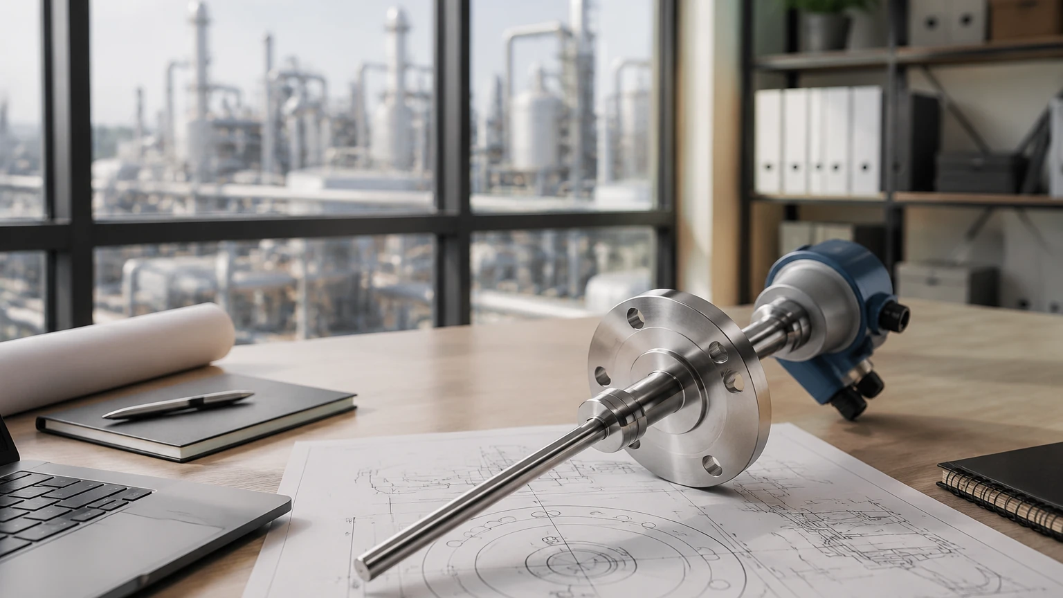
In an insertion mag flow meter, the magnetic coils and electrodes are housed within a probe head located at the end of a long stem. When the probe is inserted into the pipe, the coils generate a magnetic field perpendicular to the direction of flow. As the conductive fluid passes through this field, a voltage is generated and picked up by the electrodes on the probe surface. The transmitter then converts this micro-voltage signal into a flow rate measurement. Because the meter measures the velocity at a specific point (or a small localized area), the total volumetric flow is calculated by the transmitter using the cross-sectional area of the pipe and a profile compensation factor.
Key Advantages in Industrial Applications
The adoption of insertion mag flow meters is primarily driven by three factors: cost, convenience, and scalability.
1. Cost-Effectiveness for Large Pipes
For pipe diameters exceeding 200 mm (8 inches), the cost of a full-bore electromagnetic flow meter increases exponentially due to the amount of material and the specialized manufacturing required. In contrast, the price of an insertion mag flow meter remains relatively constant regardless of the pipe size, as the probe assembly is standardized. This makes it the preferred choice for large-scale water distribution and cooling water circuits.
2. Ease of Installation (Hot Tapping)
One of the most significant benefits is the ability to install the meter using a "hot tap" procedure. By using a ball valve and a specialized drilling tool, the probe can be inserted into a pressurized pipe without shutting down the process or draining the system. This eliminates costly downtime and the logistical challenges associated with pipe cutting and welding.
3. Low Pressure Drop
Because the probe occupies only a tiny fraction of the pipe's cross-sectional area, the permanent pressure loss is negligible. This is particularly beneficial in gravity-fed systems or applications where pumping costs must be minimized.
Technical Evaluation and Selection Criteria
Selecting the right insertion mag flow meter requires a detailed assessment of the process fluid and the mechanical environment. Before finalizing a specification, engineers should evaluate the following parameters:
Fluid Conductivity
As an electromagnetic device, the fluid must be conductive. Most industrial insertion meters require a minimum conductivity of 5 μS/cm. This makes them suitable for water, wastewater, acids, and bases, but unsuitable for hydrocarbons, distilled water, or non-aqueous chemicals.
Velocity Range
Insertion meters are most accurate within specific velocity windows, typically between 0.1 m/s and 10 m/s (0.3 to 33 ft/s). At very low velocities, the signal-to-noise ratio decreases, which can affect accuracy. Conversely, extremely high velocities may cause mechanical vibration or "vortex shedding" around the probe stem.
Material Compatibility
The wetted parts—specifically the probe body, the electrodes, and the seals—must be compatible with the process fluid.
* Probe Body: Usually 316L Stainless Steel or Hastelloy.
* Electrodes: Often made of 316L SS, Hastelloy C, Titanium, or Tantalum for corrosive environments.
* Insulation/Liner: Materials like PEEK or PTFE are used to isolate the electrodes from the probe body.
Pipe Material and Size
While insertion meters are versatile, the pipe material affects the grounding strategy. For non-conductive pipes (e.g., PVC, HDPE, or lined pipes), grounding rings or extra grounding electrodes are necessary to provide a stable reference point for the voltage measurement.
Practical Selection Table
| Feature | Specification / Requirement |
| :— | :— |
| Pipe Size Range | 50 mm to 3000 mm (2" to 120") |
| Fluid Conductivity | > 5 μS/cm (Typical) |
| Accuracy | ±1.0% to ±2.0% of rate (Application dependent) |
| Max Pressure | Up to 16 bar (Standard), 40 bar (Custom) |
| Max Temperature | Up to 150°C (302°F) depending on materials |
| Output Signals | 4-20mA, Pulse, RS485 (Modbus), HART |
| Installation Type | Threaded (NPT/G), Flanged, or Hot-tap Ball Valve |
Installation Best Practices and Considerations
The accuracy of an insertion mag flow meter is highly dependent on the flow profile at the point of measurement. Because the meter measures point velocity, any turbulence or swirl in the pipe will lead to significant errors.
Straight Pipe Run Requirements
To ensure a fully developed flow profile, the meter must be installed in a straight section of pipe. The industry standard recommendation is:
* Upstream: Minimum 10 pipe diameters (10D) of straight pipe after the nearest obstruction (elbows, valves, pumps).
* Downstream: Minimum 5 pipe diameters (5D) of straight pipe before the next obstruction.
If the upstream obstruction is a pump or a partially closed valve, the required straight run may increase to 20D or 30D.
Insertion Depth
Correct positioning of the electrodes within the pipe is critical. There are generally two methods for determining insertion depth:
1. The 1/8th Diameter Method: The electrodes are placed at 1/8th of the pipe's internal diameter. This is often considered the point of average velocity in a turbulent flow profile.
2. The Centerline Method: The electrodes are placed at the exact center of the pipe. This method is often used for smaller pipes (under 400 mm) or where specific calibration factors are applied.
Orientation
On horizontal pipes, the probe should be installed at a 45-degree or 90-degree angle from the top of the pipe. Avoid installing the probe at the very top (where air bubbles may collect) or at the very bottom (where sediment may accumulate and coat the electrodes). For vertical pipes, the flow should always be in an upward direction to ensure the pipe remains completely full.
Grounding
Electromagnetic flow meters measure very small voltages. Any stray electrical noise in the piping system can interfere with the signal. Proper grounding involves connecting the meter's grounding terminal to the process liquid. In metal pipes, this is usually achieved by bonding the meter to the pipe. In plastic pipes, grounding rings must be installed on either side of the insertion point.
Comparison: Insertion vs. Full-Bore Electromagnetic Flow Meters
When deciding between these two technologies, engineers must weigh accuracy against logistical constraints.
| Factor | Full-Bore Mag Meter | Insertion Mag Meter |
| :— | :— | :— |
| Accuracy | High (±0.2% to ±0.5%) | Moderate (±1.0% to ±2.0%) |
| Installation Cost | High (Requires pipe cutting) | Low (Single-point entry) |
| Maintenance | Low (No moving parts) | Moderate (Probe may need cleaning) |
| Pressure Loss | Zero (Same as pipe) | Negligible (Small obstruction) |
| Line Size Limit | Expensive at large sizes | Economical at all large sizes |
For high-precision billing or custody transfer applications, a full-bore meter is usually required. However, for process monitoring, cooling water management, and leak detection, the insertion mag flow meter provides sufficient accuracy at a fraction of the total cost of ownership.
Common Limitations and Operational Risks
While highly effective, insertion mag flow meters are not suitable for every application. Users should be aware of the following risks:
1. Flow Profile Sensitivity: If the straight-run requirements are not met, the meter may over-read or under-read by as much as 10-20%.
2. Electrode Coating: In fluids with high oil content or sticky particulates, a film can build up on the electrodes, insulating them and causing signal loss. Regular inspection and cleaning may be necessary in these environments.
3. Mechanical Stress: In very high-velocity applications, the probe stem is subject to significant drag forces. If the stem is too long or the velocity too high, the probe may vibrate or even bend.
4. Full Pipe Requirement: Like all electromagnetic meters, the pipe must be 100% full. The meter cannot distinguish between liquid and air; if the pipe is partially empty, the readings will be erratic and inaccurate.
Frequently Asked Questions (FAQs)
Q: Can an insertion mag flow meter be used on steam or gas?
A: No. Electromagnetic flow meters require a conductive liquid. Steam and gases do not have the necessary conductivity to generate a signal.
Q: How often does the meter need calibration?
A: In clean water applications, the calibration is typically stable for several years. However, in corrosive or abrasive fluids, an annual check is recommended to ensure the electrodes have not degraded.
Q: What is the minimum pipe size for an insertion meter?
A: While some models can fit into 50 mm (2") pipes, they are most effective and commonly used in pipes 100 mm (4") and larger. In small pipes, the probe body occupies too much of the cross-section, causing significant flow disturbance.
Q: Can I use an insertion mag meter in a plastic pipe?
A: Yes, provided you use grounding rings or a grounding probe to ensure the fluid is at the same electrical potential as the meter electronics.
Conclusion
The insertion mag flow meter is a robust and efficient tool for modern industrial fluid management. By offering a balance between performance and ease of installation, it allows facilities to implement comprehensive flow monitoring in areas where full-bore meters would be cost-prohibitive. To ensure successful implementation, project managers should carefully verify fluid conductivity, pipe geometry, and grounding requirements during the design phase.
For more detailed technical specifications and to Review product options and application support, consult with a qualified instrumentation specialist to match the meter to your specific process conditions.