How Does a Magnetic Flow Meter Work
How Does a Magnetic Flow Meter Work
In the realm of industrial process control, the ability to measure the movement of liquids with high precision is fundamental to operational efficiency, safety, and billing accuracy. Among the various technologies available, the electromagnetic flow meter—commonly referred to as a magmeter—stands out for its lack of moving parts and its ability to handle corrosive chemicals and abrasive slurries. Understanding how does a magnetic flow meter work is essential for engineers and plant managers who must select the right instrumentation for complex fluid environments.
While many industrial facilities focus heavily on storage monitoring through a Main Page of level measurement solutions, the integration of flow data provides the necessary real-time insights into dynamic processes. This guide examines the physics, construction, and practical application of magnetic flow meters in modern industry.
The Fundamental Principle: Faraday’s Law of Induction
To answer the question of how does a magnetic flow meter work, one must look to the 19th-century discoveries of Michael Faraday. The operation of a magmeter is based entirely on Faraday’s Law of Electromagnetic Induction. This law states that a voltage will be induced when a conductive medium passes through a magnetic field.
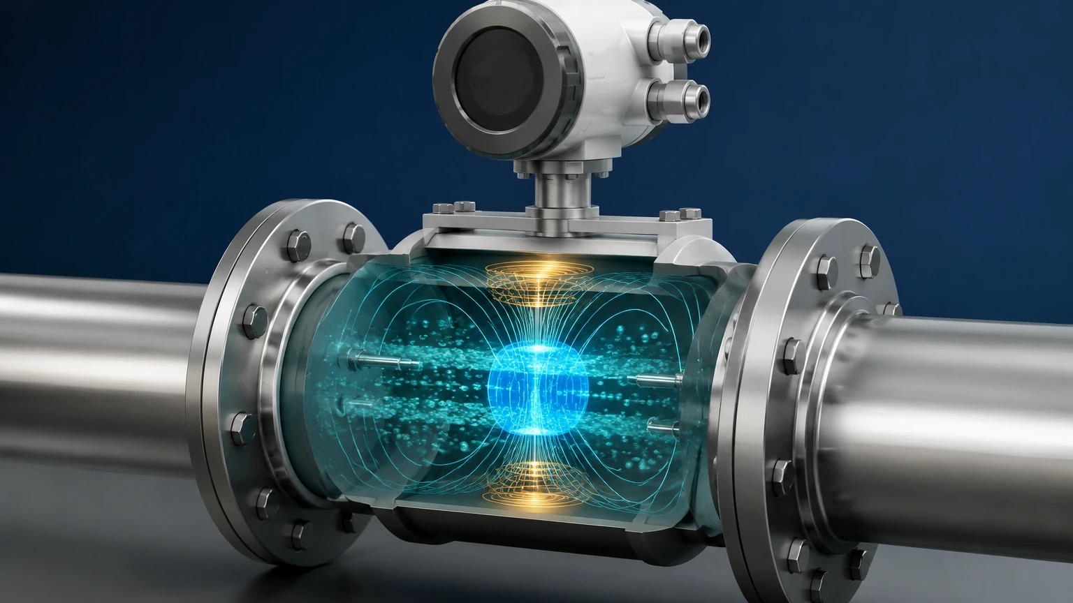
In the context of a flow meter, the "conductive medium" is the liquid flowing through the pipe. The device generates a magnetic field across the diameter of the flow tube. As the liquid moves through this field, it acts as a moving conductor, generating an electrical voltage. The mathematical relationship is expressed as:
E = k · B · D · V
Where:
* E is the induced voltage (the signal).
* k is a constant specific to the device.
* B is the strength of the magnetic field.
* D is the distance between the electrodes (typically the inner diameter of the pipe).
* V is the average velocity of the liquid.
Because the magnetic field (B) and the distance between electrodes (D) are fixed constants in a calibrated meter, the induced voltage (E) is directly proportional to the velocity (V) of the liquid. By measuring this voltage, the transmitter can calculate the volumetric flow rate with high accuracy.
Key Components of a Magnetic Flow Meter
A magnetic flow meter is comprised of two primary sections: the primary device (the flow tube installed in the pipeline) and the secondary device (the electronic transmitter).
1. The Flow Tube
This is the physical housing through which the fluid travels. It is typically constructed from non-magnetic stainless steel to ensure that the housing does not interfere with the generated magnetic field.
2. The Magnetic Coils
Two electromagnetic coils are positioned on opposite sides of the flow tube. When energized by the transmitter, these coils create a uniform magnetic field that spans the entire cross-section of the pipe.
3. The Liner
Since the flow tube is usually metal, an insulating liner is required to prevent the induced voltage from shorting out against the pipe wall. The choice of liner material is critical for chemical compatibility and temperature resistance. Common materials include PTFE (Teflon), PFA, and hard rubber.
4. Electrodes
Two electrodes are mounted flush with the liner, positioned perpendicular to both the flow direction and the magnetic field. These electrodes "pick up" the induced voltage and send it to the transmitter for processing. For aggressive fluids, electrodes may be made from Hastelloy, Tantalum, or Platinum.
5. The Transmitter
The transmitter provides the excitation current to the coils and amplifies the minute voltage signal (often in the millivolt range) from the electrodes. It converts this signal into a standard industrial output, such as 4-20mA, pulse, or digital protocols like Modbus or HART.
Technical Selection Criteria for Industrial Applications
Selecting a magmeter requires a detailed understanding of the process fluid. Unlike ultrasonic or vortex meters, magmeters have specific requirements regarding the electrical properties of the liquid.
Fluid Conductivity
The most critical requirement for a magnetic flow meter is that the fluid must be electrically conductive. Most industrial magmeters require a minimum conductivity of 5 μS/cm (microsiemens per centimeter). This makes them ideal for water, acids, bases, and slurries, but unsuitable for hydrocarbons, distilled water, or gases.
Material Compatibility Selection Table
| Component | Material Options | Typical Application |
| :— | :— | :— |
| Liner | PTFE / PFA | Highly corrosive chemicals, high temperatures |
| Liner | Hard Rubber | Water treatment, general industrial use |
| Liner | Polyurethane | Abrasive slurries, mining applications |
| Electrodes | 316L Stainless Steel | Non-corrosive liquids, water |
| Electrodes | Hastelloy C | Organic/Inorganic acids, chlorides |
| Electrodes | Tantalum | Strong oxidizing acids (Nitric, Sulfuric) |
Accuracy and Rangeability
Magmeters offer excellent accuracy, typically ranging from ±0.2% to ±0.5% of the measured value. They also feature high turndown ratios (often 100:1 or better), meaning they can accurately measure both very low and very high flow velocities within the same pipe size.
Installation Requirements and Best Practices
Even the most advanced meter will fail to provide accurate data if installed incorrectly. When considering how does a magnetic flow meter work in a real-world environment, installation geometry is paramount.
1. Full Pipe Condition
The fundamental physics of the magmeter assume that the entire cross-sectional area of the pipe is filled with liquid. If the pipe is only partially full, the meter will over-read or provide erratic signals. For this reason, magmeters are often installed in low points of piping or in vertical lines with an upward flow direction.
2. Straight Pipe Runs
To ensure a stable velocity profile, the meter requires a certain amount of straight pipe upstream and downstream. A common engineering standard is 5D (five times the pipe diameter) of straight pipe upstream and 3D downstream. If there are pumps or valves immediately preceding the meter, these requirements may increase to 10D or more.
3. Grounding
Because the induced voltage signal is extremely small, it is highly susceptible to electrical noise. Proper grounding is the most important factor in a successful installation. If the pipeline is made of conductive metal, the meter can be grounded to the pipe flanges. If the pipeline is plastic or lined, grounding rings must be used to provide a reference point for the fluid potential.
Limitations and Constraints of Electromagnetic Technology
While highly versatile, magnetic flow meters are not a universal solution. Engineers must be aware of their technical boundaries:
* Non-Conductive Fluids: As mentioned, oils, diesel, and ultra-pure water cannot be measured. For these applications, Welk's range of level measurement tools or alternative flow technologies like ultrasonic meters are required.
* Vacuum Conditions: Certain liners, particularly PTFE, can collapse or pull away from the pipe wall under vacuum conditions. If the process involves vacuum cycles, a reinforced liner or a different material like PFA is necessary.
* Temperature Limits: The maximum temperature is generally limited by the liner material, typically topping out around 150°C to 180°C for high-end fluoropolymers.
* Entrained Air: Large bubbles or significant entrained air can disrupt the magnetic field and lead to measurement errors.
Comparing Flow and Level Measurement in Process Control
In many industrial setups, flow and level measurement work in tandem to provide a complete picture of mass balance. While a magnetic flow meter tracks the rate of fluid entering a vessel, a radar or ultrasonic level meter tracks the total volume currently stored.
For example, in a chemical dosing application, the magmeter ensures the correct rate of reagent is being added, while a level sensor from the Main Page catalog ensures the tank does not overflow or run dry. Integrating these two data points allows for automated control loops that can detect leaks (e.g., if the level is dropping faster than the outflow meter indicates) and optimize pump performance.
Frequently Asked Questions (FAQ)
Q: Can a magnetic flow meter measure the flow of steam?
No. Steam is a gas and does not have the necessary electrical conductivity for Faraday's Law to apply. Magmeters are strictly for conductive liquids.
Q: Does the viscosity of the liquid affect the measurement?
Generally, no. Magnetic flow meters measure velocity independently of viscosity, density, and pressure, provided the flow remains relatively laminar or predictably turbulent and the pipe remains full.
Q: How often does a magmeter need calibration?
Because there are no moving parts to wear out, magmeters are extremely stable. In many water applications, they may only require verification every 2-5 years. However, in corrosive or abrasive applications, electrode coating or liner wear may necessitate more frequent checks.
Q: What happens if the electrodes become coated?
If the fluid is prone to leaving deposits (like calcium or fats), the electrodes can become insulated from the fluid. This will cause the signal to drift or fail. Many modern transmitters include "electrode cleaning" circuits or diagnostic alarms to alert operators to this condition.
Conclusion
Understanding how does a magnetic flow meter work allows process engineers to leverage one of the most reliable flow measurement technologies available. By utilizing Faraday’s Law, these meters provide an unobstructed flow path, minimal pressure drop, and exceptional longevity in harsh environments. When combined with robust level measurement strategies, industrial operators can achieve a high degree of precision in their automation and resource management. For those seeking to integrate comprehensive measurement solutions, reviewing the technical specifications of both flow and level instruments is the first step toward a more efficient process.