Capacitance Manometers
Capacitance Manometers
Capacitance manometers, often referred to as Capacitance Diaphragm Gauges (CDG), are among the most accurate and reliable instruments for measuring total pressure in vacuum and low-pressure environments. Unlike many other vacuum gauges that depend on the gas composition to determine pressure, capacitance manometers provide a direct measurement of the physical force exerted by the gas on a diaphragm. This characteristic makes them indispensable in semiconductor manufacturing, chemical vapor deposition (CVD), and various industrial automation processes where gas mixtures may vary.
In the broader context of industrial instrumentation, the principles governing capacitance manometers share significant commonalities with capacitive level measurement technologies used in liquid and solid monitoring. Understanding the mechanics, selection criteria, and installation requirements of these devices is essential for process engineers aiming to maintain high-precision control in critical environments.
Understanding the Principle of Capacitance Manometers
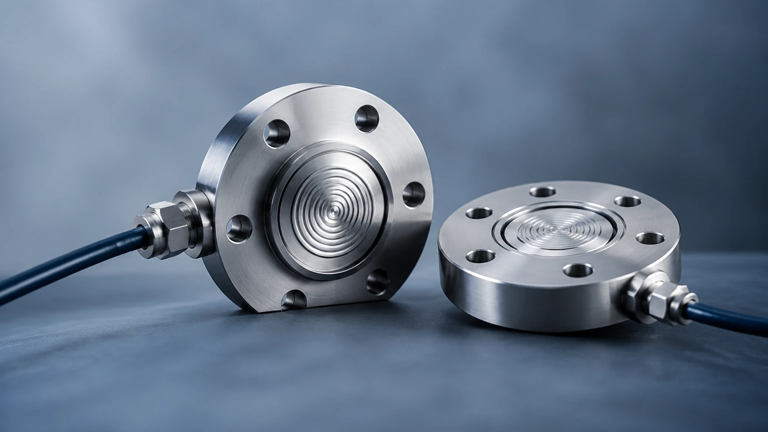
The fundamental operation of a capacitance manometer relies on the change in electrical capacitance resulting from the mechanical displacement of a diaphragm. The sensor consists of a thin, flexible metal diaphragm (usually made of a corrosion-resistant alloy like Inconel) and a fixed ceramic electrode assembly. These components are housed within a vacuum-sealed reference chamber.
The Capacitance Mechanism
When gas pressure is applied to one side of the diaphragm, it deflects toward the fixed electrode. This movement changes the distance between the diaphragm and the electrode. Since capacitance is inversely proportional to the distance between two conducting surfaces ($C = \epsilon A / d$), the deflection causes a measurable change in the electrical capacitance of the system.
Signal Conversion
An integrated electronic bridge circuit detects this change in capacitance and converts it into a high-level DC voltage signal (typically 0–10V). Because the diaphragm responds to the physical force (pressure) rather than the thermal or ionization properties of the gas, the measurement is "gas-independent." This means the gauge will read the same pressure for 100 Pa of Argon as it would for 100 Pa of Helium, a feature that distinguishes it from Pirani or thermocouple gauges.
Key Components and Construction Materials
To ensure durability and precision, capacitance manometers are constructed using materials that can withstand harsh chemical environments and provide thermal stability.
1. The Diaphragm: This is the most critical component. It must be thin enough to respond to minute pressure changes (as low as $10^{-5}$ Torr or approximately 0.0013 Pa) yet robust enough to withstand overpressure. Inconel is the standard material due to its excellent elastic properties and resistance to corrosive gases like fluorine and chlorine.
2. The Electrode: Usually made of ceramic with a gold or platinum coating, the electrode must remain perfectly stationary to ensure the capacitance change is solely due to diaphragm movement.
3. The Housing: Typically constructed from 316 stainless steel, the housing protects the internal components and provides the mechanical interface for the vacuum system.
4. Temperature Control Systems: High-end capacitance manometers often include internal heaters and thermal insulation to keep the sensor at a constant temperature (e.g., 45°C, 100°C, or 160°C). This prevents process gases from condensing on the diaphragm, which would cause measurement errors or damage.
Capacitance Manometers vs. Capacitive Level Sensors
While the capacitance manometer is designed for gas pressure measurement, the underlying physics is closely related to capacitive level sensors used in tank monitoring. In level measurement, the sensor (often a probe) acts as one plate of a capacitor, and the tank wall (or a reference probe) acts as the other. The dielectric constant of the material between them—whether liquid, powder, or air—changes as the level rises or falls, thereby changing the capacitance.
For engineers familiar with the Main Page of industrial level measurement, the transition to understanding capacitance manometers is intuitive. Both technologies require careful consideration of the dielectric properties (in the case of level) or mechanical displacement (in the case of pressure) and both rely on sophisticated electronics to filter out noise and provide a linear output. However, manometers are generally sealed units measuring a pressure differential across a physical barrier, whereas level sensors often interact directly with the medium's dielectric field.
Selection Criteria for Industrial Applications
Choosing the correct capacitance manometer requires a detailed analysis of the process environment. Engineers should evaluate the following factors:
Full-Scale Range
Capacitance manometers are available in various full-scale ranges, from 0.1 Torr (13.3 Pa) to 1000 Torr (133.3 kPa). Accuracy is highest at the upper end of the gauge's range. It is common practice to select a gauge where the normal operating pressure falls within the top 10% to 50% of the full-scale range.
Operating Temperature
* Ambient (Unheated): Suitable for clean, non-condensing gases at room temperature. These are cost-effective but prone to "zero drift" if the ambient temperature fluctuates.
* Heated (Controlled): Essential for processes involving condensable vapors (like those in semiconductor etching or CVD). By maintaining the sensor at 100°C or 160°C, the risk of deposition on the diaphragm is eliminated.
Accuracy and Linearity
Standard industrial manometers offer accuracy levels of 0.25% to 0.50% of the reading. For laboratory or calibration-grade applications, high-accuracy units can reach 0.05% of the reading. Note that "percent of reading" is a much tighter specification than "percent of full scale."
Practical Selection Table
| Application Type | Recommended Range | Temperature Control | Typical Accuracy |
| :— | :— | :— | :— |
| Load Lock Chambers | 1000 Torr (133 kPa) | Ambient | 0.50% of reading |
| Plasma Etching | 1 – 10 Torr (133 – 1333 Pa) | 45°C or 100°C | 0.15% of reading |
| Chemical Vapor Deposition | 10 – 100 Torr (1.3 – 13.3 kPa) | 100°C or 160°C | 0.12% of reading |
| Calibration Standards | Various | 45°C (Highly Stable) | 0.05% of reading |
| General Industrial Vacuum | 100 Torr (13.3 kPa) | Ambient | 0.25% of reading |
Installation and Maintenance Guidelines
Proper installation is paramount to ensuring the longevity and accuracy of a capacitance manometer. Unlike simple mechanical gauges, these are precision electronic instruments.
Mounting Orientation
Most capacitance manometers are sensitive to gravity. If a gauge is calibrated in a vertical position but installed horizontally, the weight of the diaphragm itself can cause a slight shift in the "zero" reading. It is best practice to install the gauge in the orientation specified by the manufacturer, typically with the inlet port facing downward to prevent particulates from settling on the diaphragm.
Thermal Management
For heated manometers, ensure that the surrounding area has adequate ventilation. If the gauge is insulated too heavily, the internal electronics may overheat. Conversely, if the inlet line is much colder than the heated gauge, vapors may condense in the tubing before reaching the sensor. Heat-tracing the inlet line is often necessary in high-temperature processes.
The Importance of Zeroing
Zero drift is the most common source of error in capacitance manometers. It can be caused by temperature shifts, mechanical stress, or aging of the electronics. Before taking measurements, the system should be pumped down to a pressure at least one order of magnitude below the gauge's resolution, and the "zero" button or potentiometer should be adjusted. This ensures that the 0V output corresponds exactly to a true vacuum.
Limitations and Common Risks
While highly accurate, capacitance manometers have specific limitations that must be managed:
* Overpressure Damage: Although most units can withstand a certain amount of overpressure (e.g., 150% to 200% of full scale), a sudden burst of high-pressure gas can permanently deform the diaphragm, leading to non-linear readings or total failure.
* Particulate Contamination: In processes like powder coating or certain chemical reactions, solid particles can enter the sensor. If a particle becomes lodged between the diaphragm and the electrode, the gauge will become unresponsive or provide erratic data. Using a baffle or a fine mesh filter at the inlet can mitigate this risk.
* Hysteresis: Repeatedly cycling between high vacuum and atmospheric pressure can cause slight mechanical hysteresis in the diaphragm material, though this is usually negligible in high-quality Inconel sensors.
Frequently Asked Questions (FAQ)
Q: Why is a capacitance manometer preferred over a Pirani gauge?
A: A Pirani gauge measures thermal conductivity, which varies depending on the gas type. A capacitance manometer measures physical force, making it gas-independent and significantly more accurate for precise process control involving gas mixtures.
Q: How often should a capacitance manometer be calibrated?
A: For critical semiconductor or medical applications, annual calibration is standard. However, in stable industrial environments, biennial calibration may suffice, provided that regular "zeroing" is performed.
Q: Can these gauges measure atmospheric pressure?
A: Yes, 1000 Torr models are specifically designed to measure from high vacuum up to slightly above atmospheric pressure (101.3 kPa / 1013 mbar).
Q: What is the impact of vibration on measurement?
A: Excessive vibration can introduce noise into the capacitance bridge circuit. If the gauge is mounted near a heavy vacuum pump, flexible bellows or vibration isolators should be used.
For engineers seeking comprehensive solutions in level and pressure measurement, including radar and ultrasonic technologies, it is advisable to Review product options and application support to ensure the selected instrumentation aligns with specific industrial requirements. Proper integration of capacitance-based sensors, whether for vacuum or liquid level, remains a cornerstone of modern process automation.