Radar Level Transmitter Troubleshooting
Radar Level Transmitter Troubleshooting: A Technical Guide for Industrial Applications
In modern industrial automation, the accuracy of level measurement is critical for process safety, inventory management, and operational efficiency. Radar technology has become a preferred choice for many engineers due to its non-contact nature and versatility. However, even the most advanced Radar Level Meters can encounter performance issues due to complex process conditions or improper installation. This guide provides a comprehensive technical framework for radar level transmitter troubleshooting, selection, and maintenance.
Understanding Radar Level Measurement Principles
Before addressing troubleshooting steps, it is essential to understand the underlying physics of how these instruments operate. Radar level transmitters use electromagnetic waves, typically in the microwave spectrum, to measure the distance to a liquid or solid surface.
Time of Flight (ToF)
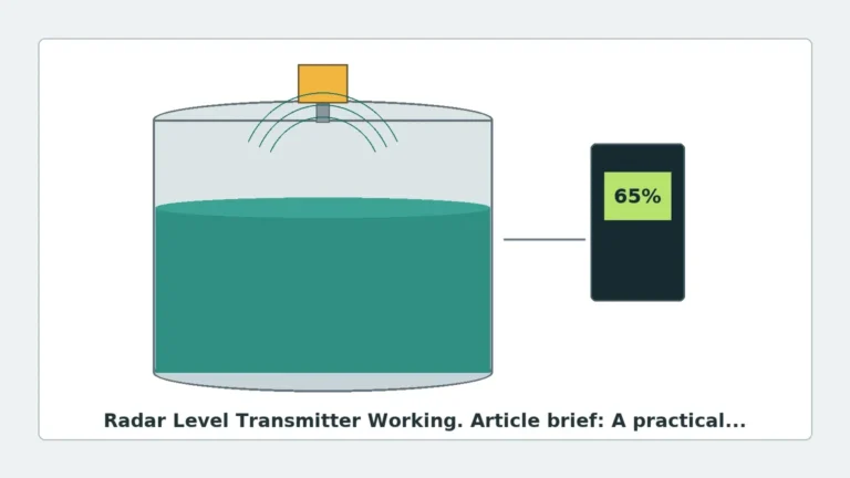
Most industrial radar sensors operate on the Time of Flight principle. The device emits a microwave pulse or a continuous wave that travels at the speed of light. When the signal hits the surface of the medium, a portion of the energy is reflected back to the sensor. The transmitter calculates the distance based on the time elapsed between emission and reception.
FMCW vs. Pulse Radar
There are two primary modulation techniques used in industrial radar:
1. Pulse Radar: The transmitter sends short microwave pulses and measures the time delay. This technology is often used in battery-powered or low-power applications.
2. FMCW (Frequency Modulated Continuous Wave): The transmitter emits a continuous signal with a constantly changing frequency. The difference in frequency between the emitted and reflected signal is proportional to the distance. FMCW is generally more accurate and provides a better signal-to-noise ratio, making it ideal for complex industrial environments.
Frequency Bands
The frequency of the radar (e.g., 6GHz, 26GHz, or 80GHz) significantly impacts performance. Higher frequencies, such as 80GHz, allow for smaller antenna sizes and narrower beam angles (as tight as 3°), which helps in avoiding internal tank obstructions like agitators or heating coils.
Essential Radar Level Transmitter Troubleshooting Steps
When a radar level transmitter fails to provide accurate readings, the following systematic approach should be used to identify and resolve the issue.
1. Verification of Power and Signal Loop
Before investigating the process environment, ensure the hardware is functioning correctly. Check the supply voltage at the transmitter terminals (typically 24V DC). In 4-20mA loop-powered systems, ensure the loop resistance is within the manufacturer's specified limits (usually 250 to 500 ohms for HART communication). If the display is blank or the signal is stuck at 3.6mA or 21mA, it often indicates a hardware failure or a critical error state.
2. Analyzing the Echo Curve (Envelope Curve)
Modern radar level meters provide a digital representation of the reflected signals, known as an echo curve or envelope curve. This is the most powerful tool for radar level transmitter troubleshooting.
* True Echo: The reflection from the actual material surface.
* False Echoes: Reflections from agitators, ladders, or build-up on the tank walls.
* Multiple Reflections: Occur when the signal bounces between the surface and the tank roof.
If the transmitter is locking onto a false echo, the "Echo Mapping" or "False Echo Suppression" function must be used to tell the device to ignore these static reflections.
3. Addressing Signal Loss
If the device reports a "Loss of Echo," the reflected signal is too weak to be detected. This can be caused by:
* Low Dielectric Constant (DK): Materials with a DK below 1.5 (like some hydrocarbons or liquefied gases) reflect very little energy.
* Heavy Foam: Certain types of thick, dense foam can absorb the radar signal entirely.
* Surface Turbulence: Extreme agitation can scatter the radar waves away from the antenna.
4. Handling Fluctuating Readings
If the level reading jumps erratically, check for electromagnetic interference (EMI) or physical interference. Ensure the cable shielding is grounded at only one end to prevent ground loops. In the software settings, increasing the "Damping Time" or "Integration Time" can help smooth out fluctuations caused by surface waves.
Installation Constraints and Best Practices
Many troubleshooting issues stem from improper installation. Adhering to the following constraints will minimize measurement errors.
Nozzle Design and Mounting Position
* Avoid the Center: Never mount a radar transmitter in the exact center of a domed tank. This can lead to multiple reflections that converge at the center, causing signal interference.
* Wall Distance: The sensor should be installed at least 200mm to 500mm from the tank wall to avoid interference from wall weld seams or build-up.
* Nozzle Height: The antenna should ideally extend past the bottom of the mounting nozzle. If the antenna is recessed deep within a narrow nozzle, the signal will reflect off the nozzle walls, creating a large "dead zone" at the top of the tank.
Obstructions in the Beam Path
The radar beam spreads as it travels (the beam angle). Any physical object within this cone—such as pipes, ladders, or agitator blades—will create a reflection. If an obstruction cannot be moved, a higher-frequency radar (80GHz) should be selected to provide a narrower beam that bypasses the object.
Selection Criteria for Reliable Radar Level Meters
Choosing the right instrument for the specific application is the first step in preventing future troubleshooting needs. Use the following table as a general selection guide.
| Application Feature | Recommended Radar Type | Reasoning |
| :— | :— | :— |
| Large Silos (Solids) | 80GHz FMCW | Narrow beam avoids wall contact; high frequency penetrates dust. |
| Small Tanks with Agitators | 80GHz FMCW | Narrow beam avoids agitator blades. |
| Corrosive Chemicals | PTFE Encapsulated Antenna | Protects the sensor from chemical attack. |
| High Pressure/Temperature | Metallic Horn with Seal | Ensures process containment and durability. |
| Low Dielectric Liquids | Guided Wave Radar (GWR) | Directs energy along a probe to maximize reflection. |
| Open Channels/Water | 26GHz or 80GHz Pulse/FMCW | Cost-effective and unaffected by ambient conditions. |

Application Risks and Limitations
While radar is highly robust, engineers must be aware of its factual limitations:
1. Dielectric Constant (εr): This is the most critical factor. If the εr is too low, the signal passes through the material rather than reflecting. For materials with εr < 2.0, a stilling well or a Guided Wave Radar may be necessary.
2. Vacuum and Pressure: While the radar signal itself is unaffected by vacuum or high pressure, the physical housing and seals of the transmitter must be rated for the specific process pressure.
3. Steam and Condensation: While radar penetrates steam better than ultrasonic sensors, heavy condensation on the antenna lens can cause signal attenuation. In these cases, a parabolic antenna or a lens with a specialized "drip-off" design is recommended.
4. Dust and Build-up: In solid applications, heavy dust can attenuate the signal. Furthermore, if the material is conductive and sticky (like wet coal), build-up on the antenna can completely block the signal.
Practical Troubleshooting and Maintenance Table
| Symptom | Probable Cause | Recommended Action |
| :— | :— | :— |
| Reading stuck at tank top | Condensation or build-up on antenna | Clean antenna; check if purging is required. |
| Reading stuck at a fixed point | Internal obstruction (ladder/pipe) | Perform False Echo Mapping; check beam angle. |
| "Loss of Echo" error | Low DK or heavy foam | Check DK value; consider Guided Wave Radar. |
| Inaccurate reading (offset) | Incorrect Tank Height setting | Re-measure tank height and update parameters. |
| Signal drops during filling | Turbulence or dust clouds | Increase damping; check antenna alignment. |
| Erratic output (4-20mA) | Loop interference or low voltage | Check cable shielding and power supply voltage. |
Buyer Confirmation Checklist
When procuring a radar level meter, international buyers should confirm the following technical details with the manufacturer to ensure application compatibility:
* Process Medium: What is the material, and what is its dielectric constant?
* Vessel Geometry: Provide the tank height, diameter, and a diagram of internal obstructions.
* Process Conditions: What are the maximum and minimum operating temperatures and pressures?
* Mounting Connection: What is the flange or thread size? Is there a nozzle height restriction?
* Output Requirements: Is a standard 4-20mA/HART signal sufficient, or is Modbus/RS485 required?
* Hazardous Area Rating: Does the environment require ATEX, IECEx, or other explosion-proof certifications?
Frequently Asked Questions (FAQ)
Q: Can radar level meters measure through plastic tanks?
A: Yes. If the tank is made of a non-conductive material like PE, PP, or PVC, and the wall is not too thick, the radar signal can pass through the tank roof to measure the level without a process opening.
Q: How does foam affect radar measurement?
A: It depends on the foam density. Light, airy foam is usually transparent to radar. However, dense, wet foam can absorb or scatter the signal. In such cases, 6GHz or 26GHz radars often perform better than 80GHz, or a Guided Wave Radar should be used.
Q: Is it necessary to recalibrate radar meters annually?
A: Generally, no. Radar level meters have no moving parts and do not suffer from mechanical wear. Calibration is usually only required if regulated by local safety standards or if the process medium changes significantly in a way that affects the signal velocity (though this is rare for radar compared to ultrasonic).
Q: What is the "Dead Zone" or "Blocking Distance"?
A: This is the area immediately below the antenna where the device cannot measure accurately. It is caused by the time required for the electronics to switch from transmit to receive mode. It is typically between 50mm and 300mm depending on the frequency and antenna type.
By following these engineering principles and troubleshooting steps, plant operators can ensure that their Radar Level Meters provide reliable data for years of service in even the most demanding industrial environments.