Radar Level Transmitter Types
Radar Level Transmitter Types: A Comprehensive Engineering Guide to Selection and Application
In the landscape of industrial process automation, accurate level measurement is critical for inventory management, process safety, and operational efficiency. Among the various technologies available, radar level measurement has emerged as a premier solution due to its non-contact nature and ability to withstand extreme process conditions. However, selecting the correct equipment requires a deep understanding of the various radar level transmitter types and their underlying physics.
This guide examines the technical principles, categorization, and practical selection criteria for radar level transmitters, providing engineers and procurement professionals with the factual foundation needed to specify instrumentation for complex industrial environments.
1. Fundamental Measurement Principles
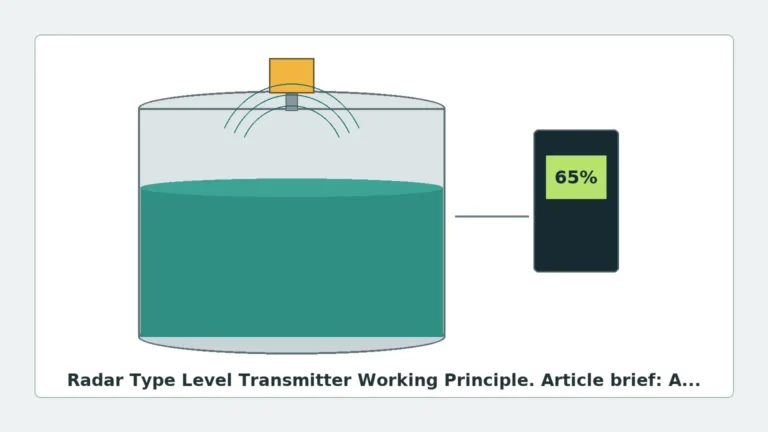
Before exploring specific radar level transmitter types, it is essential to understand how radar technology interacts with process media. Radar level meters utilize electromagnetic waves, typically in the microwave spectrum, to determine the distance from a reference point (the sensor) to the surface of a material.
Time of Flight (ToF)
The most basic principle used is Time of Flight. The transmitter emits a microwave pulse that travels at the speed of light. When the pulse hits the surface of the medium, a portion of the energy is reflected back to the sensor. The distance ($D$) is calculated using the formula:
$$D = \frac{c \times t}{2}$$
Where:
* $c$ is the speed of light (approximately 300,000 km/s).
* $t$ is the measured transit time.
The Role of Dielectric Constant ($ε_r$)
The reliability of the reflection depends heavily on the Dielectric Constant ($ε_r$) of the medium. Materials with high dielectric constants, such as water ($ε_r ≈ 80$), reflect signals strongly. Hydrocarbons and oils often have low dielectric constants ($ε_r < 2.0$), which can result in weaker return signals, requiring more sensitive radar level transmitter types or guided wave solutions.
—
2. Major Radar Level Transmitter Types by Technology
Industrial radar transmitters are broadly categorized by their signal modulation methods: Pulse Radar and Frequency Modulated Continuous Wave (FMCW).
Pulse Radar
Pulse radar transmitters emit microwave energy in short, discrete bursts. Between pulses, the sensor "listens" for the returning echo.
* Advantages: Lower power consumption, making them suitable for two-wire loop-powered circuits.
* Limitations: Generally lower accuracy compared to FMCW and can struggle with high levels of surface turbulence or foam.
FMCW (Frequency Modulated Continuous Wave)
FMCW radar does not send pulses; instead, it emits a continuous signal with a constantly changing frequency (a sweep). The distance is determined by the frequency difference between the emitted signal and the reflected signal at any given moment.
* Advantages: Extremely high precision (up to ±1 mm), better signal-to-noise ratio, and superior performance in agitated tanks or with low-dielectric materials.
* Applications: Custody transfer and high-precision process control.
—
3. Categorization by Physical Configuration
When evaluating Radar Level Meters, the most significant distinction in radar level transmitter types is between non-contact and contact (Guided Wave) designs.
Non-Contact Radar (Free-Space Radar)
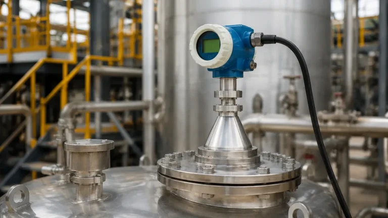
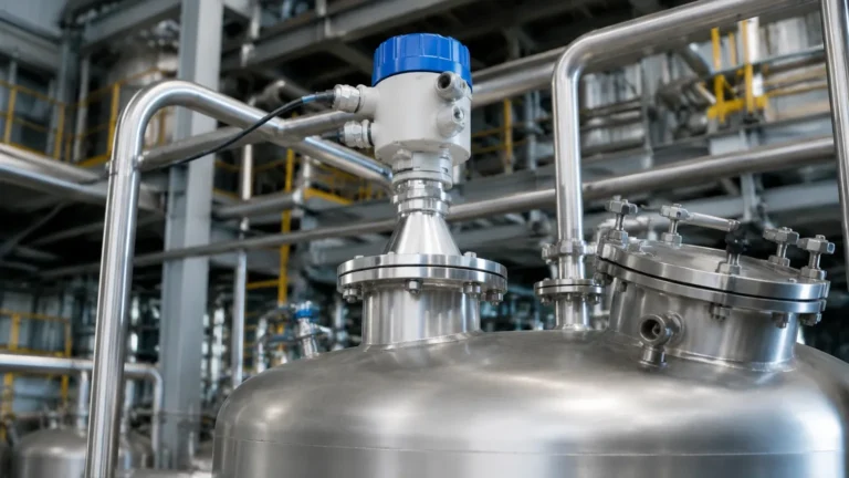
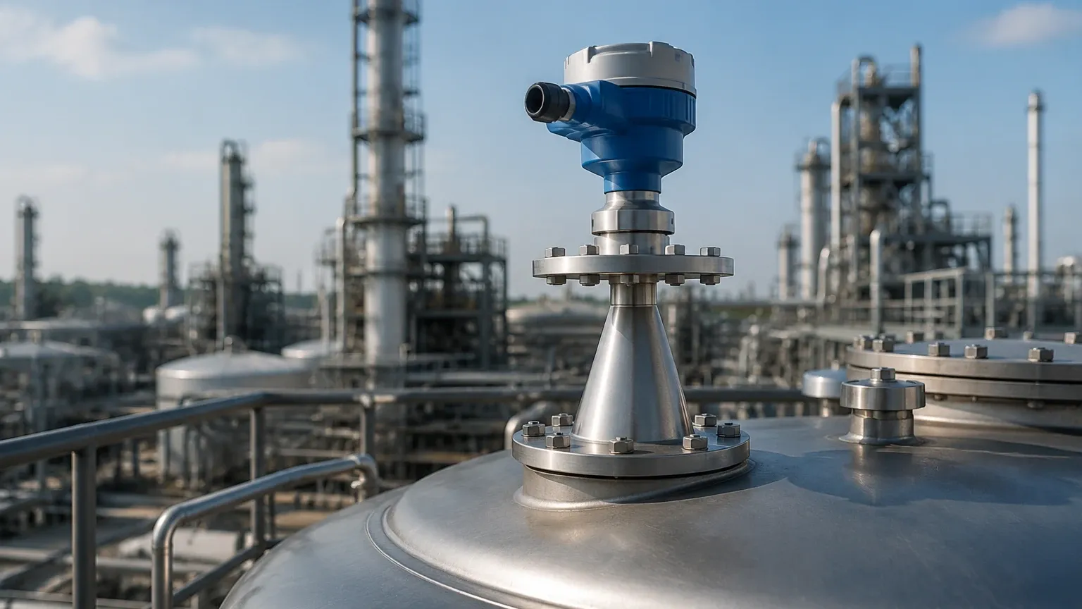
These instruments are mounted at the top of a vessel and emit waves through the air or vapor space. They are the preferred choice when the medium is corrosive, abrasive, or must remain sterile.
* 6GHz Radar: Features a lower frequency with a longer wavelength. It is less affected by steam or dust but requires a large antenna (horn) to achieve a focused beam.
* 26GHz Radar: The current industrial workhorse. It offers a balance of small antenna size and good signal focusing, suitable for most standard chemical and water treatment applications.
* 80GHz Radar: The latest advancement in non-contact technology. The high frequency allows for a very narrow beam angle (often as small as 3°), which avoids internal tank obstructions like agitators or heating coils.
Guided Wave Radar (GWR)
GWR is a contact-based radar technology. The microwave signal is guided along a physical probe (rod, cable, or coaxial tube) rather than being broadcast through free space.
* High Efficiency: Because the signal is concentrated around the probe, there is minimal energy loss. This makes GWR ideal for liquids with very low dielectric constants ($ε_r$ as low as 1.4).
* Stability: GWR is unaffected by surface foam, dust, or heavy vapor, as the probe maintains a direct path to the liquid surface.
—
4. Selection Criteria and Comparison Table
Selecting between different radar level transmitter types requires balancing process conditions against instrument capabilities. The table below provides a general engineering reference for selection.
| Feature | Guided Wave Radar (GWR) | 26GHz Non-Contact | 80GHz Non-Contact |
| :— | :— | :— | :— |
| Measurement Type | Contact (Probe) | Non-Contact | Non-Contact |
| Standard Accuracy | ±2 mm to ±5 mm | ±3 mm to ±10 mm | ±1 mm to ±2 mm |
| Max Range | Up to 30m (cable) | Up to 30m – 70m | Up to 120m |
| Beam Angle | N/A (signal follows probe) | 10° – 20° | 3° – 8° |
| Effect of Foam | Minimal | Moderate | Significant (frequency dependent) |
| Low Dielectric Media | Excellent | Fair | Good (with FMCW) |
| Internal Obstructions | Ignores them | Sensitive to them | Easily avoids them |
—
5. Installation Considerations and Engineering Constraints
Proper installation is as critical as selecting the right radar level transmitter types. Failure to follow geometric constraints often leads to "false echoes" and signal loss.
The Blind Zone (Blocking Distance)
Every radar transmitter has a minimum distance near the antenna where it cannot measure accurately. For non-contact radar, this is typically 100mm to 500mm depending on the antenna type. For GWR, the blind zone exists at both the top (near the flange) and the bottom (end of the probe).
Nozzle Geometry
The mounting nozzle should be as short and wide as possible. If a nozzle is too long or narrow, the radar signal may reflect off the nozzle walls before even entering the tank, creating a massive interference signal.
Obstruction Avoidance
* Non-contact: The "beam spread" must be calculated. If the beam hits a ladder or a pipe, it will report a false level. 80GHz transmitters are often used to solve this due to their narrow beam.
* GWR: The probe must not touch the tank wall or any internal metal structures, as this will cause a short-circuit of the microwave signal.
Pressure and Temperature
Standard radar units typically handle up to 40 bar and 150°C. For high-pressure steam boilers or molten salt applications, specialized high-temperature antennas with ceramic seals and cooling fins are required.
—
6. Application Risks and Limitations
While radar is highly versatile, it is not a universal solution. Engineers should be aware of the following limitations:
1. Heavy Foam: Extremely thick, dense foam (like shaving cream) can absorb the radar signal entirely, preventing a return echo. In these cases, Guided Wave Radar or ultrasonic sensors may be more appropriate.
2. Vacuum Conditions: While radar works in a vacuum (unlike ultrasonic), the mechanical seals of the transmitter must be rated for vacuum to prevent air ingress or sensor damage.
3. Conductive Dust: In solid level measurement (e.g., carbon black), conductive dust can coat the antenna. If the coating becomes thick enough, it can attenuate the signal. Air purging systems are often used to keep the antenna clean.
—
7. International Procurement Checklist
For international buyers and system integrators, confirming technical specifications before shipment is vital to ensure site compatibility. Ensure the following data points are verified:
* Process Connection: Threaded (G or NPT) or Flanged (ANSI, DIN, JIS). Specify the exact size and pressure rating.
* Output Protocol: Is 4-20mA sufficient, or is HART, Modbus RS485, or Profibus required for digital integration?
* Hazardous Area Ratings: Does the site require ATEX (Europe), IECEx (International), or UL/CSA (North America) explosion-proof certifications?
* Medium Properties: Provide the Dielectric Constant ($ε_r$), density (for GWR interface), and the presence of corrosive chemicals requiring PTFE or Hastelloy wetted parts.
—
8. Frequently Asked Questions (FAQ)
Q: Can radar level transmitters measure the interface between two liquids?
A: Yes, specifically Guided Wave Radar. It can measure both the total level and the interface level (e.g., oil over water), provided the upper liquid has a lower dielectric constant than the lower liquid.
Q: Is 80GHz always better than 26GHz?
A: Not necessarily. While 80GHz offers better precision and narrower beams, 26GHz is often more cost-effective and performs better in extremely dusty environments where high-frequency signals might suffer more scattering.
Q: How does agitation affect radar measurement?
A: Surface turbulence causes the signal to scatter. FMCW radar level transmitter types with advanced software algorithms can filter this noise, but in extreme cases, a stilling well or a Guided Wave Radar probe is recommended to provide a stable surface for measurement.
Q: Do radar transmitters require periodic calibration?
A: Unlike mechanical gauges, radar transmitters have no moving parts and do not suffer from mechanical wear. Periodic "verification" is recommended, but the electronic calibration typically remains stable for years unless the process medium properties change drastically.
By understanding these radar level transmitter types and their operational boundaries, industrial facilities can ensure reliable, long-term level monitoring even in the most challenging process environments.