Magnetic Flow Transmitter Working Principle
Magnetic Flow Transmitter Working Principle
In the realm of industrial process control, the ability to measure the flow of conductive liquids with high precision and minimal maintenance is critical. The magnetic flow transmitter, often referred to as a magmeter, has become a cornerstone technology for industries ranging from wastewater treatment to chemical processing. Unlike mechanical flow meters that rely on moving parts, the magnetic flow transmitter utilizes electromagnetic properties to determine flow velocity, offering a solution that is both robust and highly accurate.
Understanding the magnetic flow transmitter working principle is essential for engineers and technicians tasked with selecting, installing, and maintaining these instruments. As a professional manufacturer of industrial measurement solutions, Welk provides this technical guide to help process professionals navigate the complexities of electromagnetic flow measurement. For a broader overview of industrial instrumentation, including level measurement technologies, you may visit our Main Page.
The Fundamentals of Electromagnetic Induction
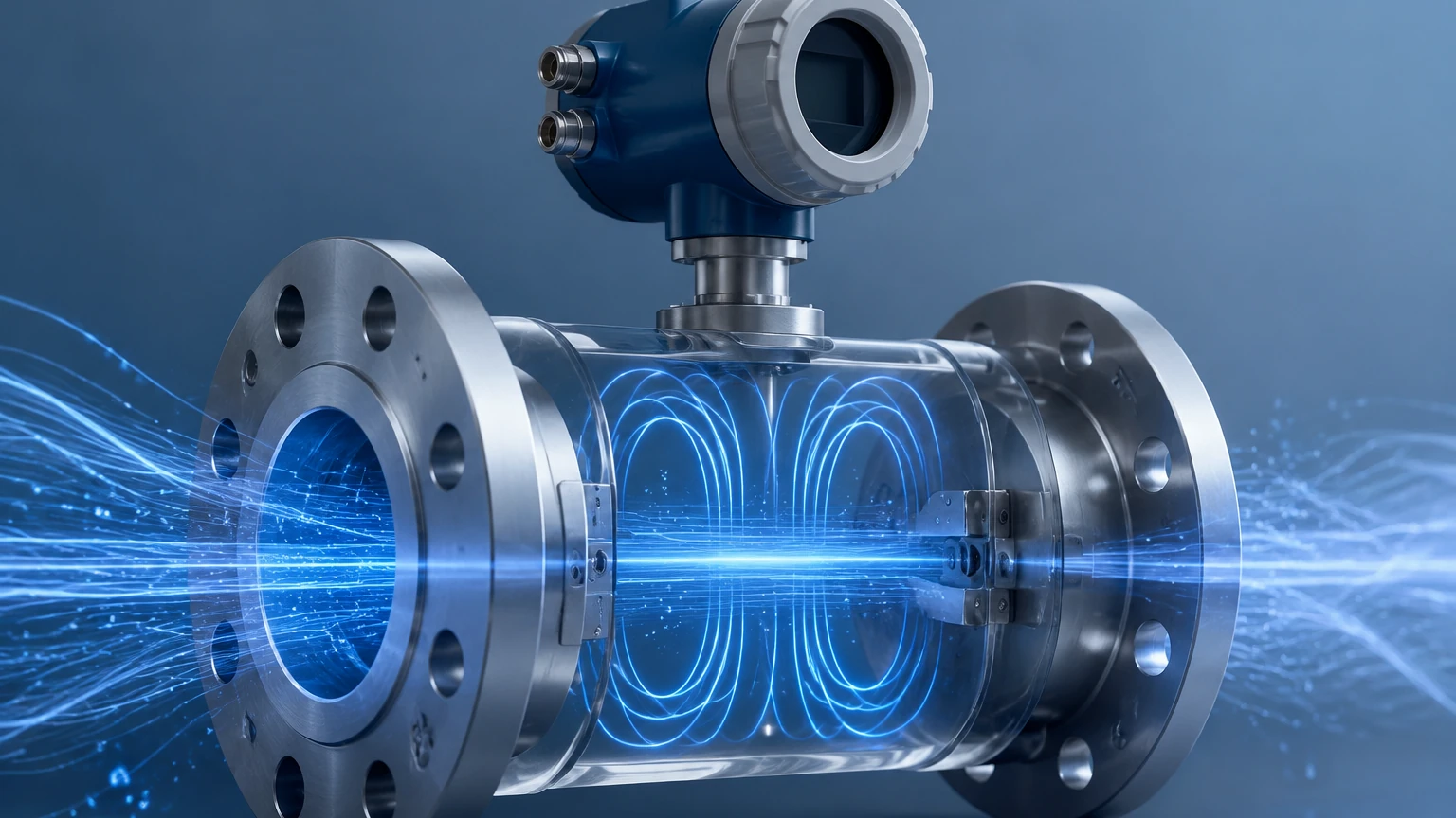
The fundamental magnetic flow transmitter working principle is based on Faraday’s Law of Electromagnetic Induction, first formulated by Michael Faraday in 1831. This law states that a voltage is induced when a conductive medium passes through a magnetic field. In the context of a flow meter, the "conductive medium" is the liquid flowing through the pipe, and the "magnetic field" is generated by the meter’s internal coils.
The Mathematical Formula
The relationship between the induced voltage and the flow velocity is expressed by the following equation:
E = k × B × D × V
Where:
* E is the induced voltage (the signal generated by the flow).
* k is a constant specific to the instrument (calibration factor).
* B is the magnetic field strength.
* D is the distance between the electrodes (typically the inner diameter of the pipe).
* V is the average velocity of the conductive liquid.
Because the magnetic field strength (B) and the distance between electrodes (D) are kept constant by the design of the meter, the induced voltage (E) is directly and linearly proportional to the velocity (V) of the fluid. This linearity is one of the primary advantages of magmeters, as it allows for accurate measurement across a wide range of flow rates (turndown ratios).
Key Components of a Magnetic Flow Transmitter
A magnetic flow transmitter consists of two primary assemblies: the flow sensor (the part installed in the pipeline) and the transmitter (the electronic unit that processes the signal). Understanding how these components interact is vital to grasping the magnetic flow transmitter working principle.
1. The Flow Tube and Liner
The flow tube is the main body through which the liquid passes. Since the measurement principle requires an electromagnetic field, the tube itself is usually made of non-magnetic stainless steel. To prevent the induced voltage from shorting out against the metal tube, the interior is lined with an insulating material. Common liners include PTFE (Teflon), PFA, and Neoprene, chosen based on the chemical compatibility and temperature of the process fluid.
2. Electromagnetic Coils
Two electromagnetic coils are positioned on opposite sides of the flow tube (usually top and bottom). When energized by the transmitter, these coils generate a constant magnetic field that permeates the entire cross-section of the pipe.
3. Electrodes
A pair of electrodes is mounted flush with the pipe wall, positioned perpendicular to both the flow direction and the magnetic field. These electrodes "pick up" the millivolt-level voltage induced by the moving fluid and send it to the transmitter for processing.
4. The Transmitter Electronics
The transmitter serves as the "brain" of the system. it provides the excitation current to the coils to create the magnetic field and receives the low-level voltage signal from the electrodes. It then filters, amplifies, and converts this signal into a standard industrial output, such as a 4-20mA analog signal, pulse output, or digital communication (HART, Modbus, or Profibus).
Selection Criteria: Materials and Fluid Compatibility
Selecting the right magnetic flow transmitter requires matching the meter's materials to the specific properties of the process liquid. The two most critical components to specify are the liner and the electrodes.
Liner Material Selection
| Material | Temperature Range | Typical Applications |
| :— | :— | :— |
| PTFE (Teflon) | -20°C to +120°C | Strong acids, bases, and corrosive chemicals. |
| PFA | -40°C to +180°C | High-temperature processes and vacuum applications. |
| Neoprene | -10°C to +80°C | General water treatment and mild abrasives. |
| Polyurethane | -10°C to +60°C | Highly abrasive slurries and mining applications. |
| Hard Rubber | 0°C to +90°C | Municipal water and wastewater. |
Electrode Material Selection
| Material | Application Characteristics |
| :— | :— |
| Stainless Steel 316L | Standard for water and non-corrosive liquids. |
| Hastelloy C | Excellent for salt water and moderate acids. |
| Titanium | Resistant to chlorides and seawater. |
| Tantalum | Highly resistant to almost all chemicals, including concentrated acids. |
| Platinum/Iridium | Used for the most extreme corrosive environments. |
Installation Best Practices for Accurate Measurement
To ensure the magnetic flow transmitter working principle functions correctly in a real-world environment, strict installation guidelines must be followed. Failure to do so can result in signal noise or inaccurate readings.
1. Straight Pipe Requirements
Flow profiles must be stable for accurate measurement. Standard practice requires a minimum of 5D (five times the pipe diameter) of straight pipe upstream of the meter and 2D of straight pipe downstream. This minimizes turbulence caused by elbows, valves, or pumps.
2. Ensuring a Full Pipe
The magmeter calculates flow based on the assumption that the cross-sectional area of the pipe is completely filled with liquid. If the pipe is only partially full, the meter will overstate the flow rate. Therefore, meters should be installed in low points of the piping system or in vertical lines with upward flow.
3. Grounding
Since the induced voltage signal is extremely small (often in the millivolt range), it is highly susceptible to electrical noise. Proper grounding is essential. The process fluid, the flow sensor, and the transmitter must all be at the same electrical potential. In metal piping systems, this is achieved by bonding the meter to the pipe flanges. In plastic or lined piping, grounding rings must be installed to provide contact with the fluid.
4. Orientation
While magmeters can be installed horizontally or vertically, horizontal installations should position the electrodes on the sides (3 and 9 o'clock positions). This prevents air bubbles at the top of the pipe or sediment at the bottom from interfering with the electrode contact.
Limitations and Application Boundaries
While magnetic flow transmitters are highly versatile, they are not suitable for every application. Understanding these limitations prevents costly misapplications.
* Conductivity Requirements: The fluid must have a minimum level of electrical conductivity, typically at least 5 μS/cm (microsiemens per centimeter). This means magmeters cannot measure petroleum-based fluids (oils), pure chemicals with no conductivity, or deionized water.
* Gas and Steam: Magmeters cannot measure the flow of gases or steam, as these media are non-conductive.
* Vacuum Conditions: Some liners, particularly PTFE, can collapse or peel away from the tube wall under vacuum conditions. PFA liners with stainless steel mesh reinforcement are preferred for vacuum service.
* Abrasive Solids: While magmeters handle slurries better than most meters, high concentrations of sharp or heavy solids can wear down the liner over time. Selecting a hardened liner like polyurethane is necessary for these environments.
Frequently Asked Questions (FAQs)
Q: Can a magnetic flow transmitter measure flow in both directions?
A: Yes, most modern magmeters are bi-directional. The transmitter can be configured to track flow in both the forward and reverse directions, providing separate totals for each.
Q: What happens if the fluid contains air bubbles?
A: Air bubbles are non-conductive. If they pass over the electrodes, they will cause signal noise and measurement errors. If the volume of air is significant, the meter may report a higher-than-actual flow because it cannot distinguish between the volume of the liquid and the volume of the air.
Q: How often does a magnetic flow transmitter need calibration?
A: Because there are no moving parts to wear out, magmeters are exceptionally stable. In many water applications, they can operate for several years without recalibration. However, in corrosive or abrasive applications, annual verification is recommended to ensure liner and electrode integrity.
Q: Does the viscosity of the liquid affect the measurement?
A: No. The magnetic flow transmitter working principle is independent of viscosity, density, and pressure, provided the flow remains within the velocity limits of the meter (typically 0.3 m/s to 10 m/s).
Conclusion
The magnetic flow transmitter is a highly reliable and accurate tool for industrial liquid measurement, provided the fluid meets the minimum conductivity requirements. By leveraging Faraday's Law, these meters offer a maintenance-free, obstructionless path that is ideal for challenging fluids like wastewater, slurries, and chemicals.
When selecting a flow or level measurement solution, it is vital to partner with a manufacturer that understands the nuances of application engineering. At Welk, we specialize in providing robust instrumentation tailored to your specific process needs. For more information on our complete range of radar, ultrasonic, and magnetic measurement technologies, please visit our Main Page.
Download Magnetic Flow Transmitter Working Principle as a PDF