Radar Level Measurement the User’s Guide
Radar Level Measurement the User's Guide
In the landscape of industrial automation, precise inventory management and process control depend heavily on reliable level instrumentation. Radar level measurement has emerged as a premier technology due to its non-contact nature, high accuracy, and resistance to varying process conditions. This radar level measurement the user's guide provides a technical overview of the principles, selection criteria, and installation best practices for engineers and procurement professionals.
1. Understanding Radar Measurement Principles
Radar level instruments operate by emitting electromagnetic waves (microwaves) toward a product surface and measuring the reflected signal. Unlike ultrasonic sensors, which rely on sound waves and are affected by air temperature and pressure, radar signals travel at the speed of light and are largely independent of the vapor space composition.
There are two primary methods used in modern Radar Level Meters:
Pulse Radar (Time-of-Flight)
Pulse radar sensors emit a short microwave pulse toward the medium. The instrument measures the time elapsed between the emission and the reception of the reflected signal. Since the speed of light is constant, the distance is calculated as:
*Distance = (Speed of Light × Travel Time) / 2*
Pulse radar is generally energy-efficient and suitable for simple applications, though it may struggle with low-dielectric materials or extremely turbulent surfaces.
FMCW (Frequency Modulated Continuous Wave)
FMCW radar emits a continuous signal with a constantly changing frequency. The reflected signal is compared to the emitted signal at that moment. The difference in frequency (the "beat frequency") is directly proportional to the distance. FMCW technology typically offers higher accuracy and a better signal-to-noise ratio than pulse radar, making it the preferred choice for complex industrial environments or low-reflectivity liquids.
2. Non-Contact vs. Guided Wave Radar (GWR)
When selecting a radar system, the first decision is often between non-contact and guided wave configurations.
* Non-Contact Radar: These instruments are mounted at the top of the vessel and emit waves through the air. They are ideal for corrosive or abrasive materials because no part of the sensor touches the medium. They are maintenance-free but can be affected by heavy foam or extremely agitated surfaces.
* Guided Wave Radar (GWR): These use a physical probe (rod or cable) to guide the microwave signal to the surface. GWR is highly effective for low-dielectric liquids (like oils) and is unaffected by turbulence, foam, or dust. However, because the probe is submerged, material compatibility with the probe metal and seals must be confirmed.
3. The Role of Frequency in Selection
The frequency of a radar meter significantly impacts its performance, specifically regarding the beam angle and its ability to penetrate dust or steam.
| Frequency | Beam Angle | Typical Applications |
| :— | :— | :— |
| 6 GHz (C-Band) | Wide (approx. 20-30°) | Large tanks with heavy steam, agitation, or foam. More tolerant of condensation. |
| 26 GHz (K-Band) | Medium (approx. 8-10°) | General purpose for liquids and solids. Good balance of size and performance. |
| 80 GHz (W-Band) | Narrow (approx. 3-4°) | Small vessels, narrow nozzles, and high-precision requirements. Excellent for solids. |
High-frequency (80 GHz) radar allows for smaller antenna sizes and a narrower beam, which helps avoid internal obstructions like ladders or agitators. However, lower frequencies are often more robust in applications with heavy condensation or buildup on the antenna.
4. Key Selection Criteria
To ensure the longevity and accuracy of the instrument, several process parameters must be analyzed during the specification phase.
Dielectric Constant (εr)
The dielectric constant of the medium determines how much of the radar signal is reflected. Materials with high εr (e.g., water, εr ≈ 80) reflect signals strongly. Materials with low εr (e.g., hydrocarbons, εr < 2) reflect very little energy. For low-dielectric materials, GWR or high-sensitivity FMCW radar is required.
Temperature and Pressure
Standard radar units typically handle up to 150°C (302°F) and 40 bar (580 psi). For extreme applications, such as boiler drum level or molten metal, specialized high-temperature antennas and ceramic seals are necessary to prevent instrument failure.
Vessel Geometry and Internal Obstacles
The presence of heating coils, agitators, or support beams can create "false echoes." Modern radar software includes "False Echo Suppression" to map out these static reflections, but choosing a mounting location with a clear line of sight is always the best engineering practice.
5. Installation Guidelines and Constraints
Proper installation is critical for the performance of Radar Level Meters. The following rules should be followed:
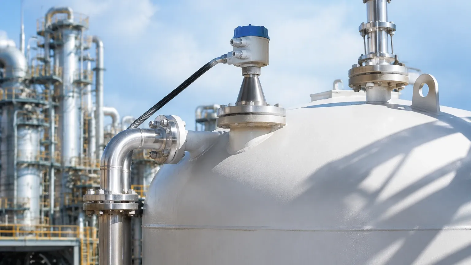
1. Avoid the Center: Do not mount the radar in the exact center of a domed tank. This can cause multiple reflections that interfere with the signal. A common rule is to mount the sensor at 1/6th of the tank diameter from the wall.
2. Nozzle Height and Diameter: The antenna should ideally extend slightly below the mounting nozzle to prevent signal interference from the nozzle edge. If using a high-frequency (80 GHz) radar, longer nozzles are more tolerable due to the narrow beam.
3. Inflow Streams: Never mount the sensor directly above the filling inlet. The falling material will reflect the signal and cause erratic readings.
4. Obstruction Clearance: Ensure the "signal cone" (based on the beam angle) does not intersect with ladders, pipes, or agitator blades. If an obstruction is unavoidable, use a radar with a narrower beam or install a stilling well.
6. Comparison with Other Technologies
| Feature | Radar (Non-Contact) | Ultrasonic | Hydrostatic |
| :— | :— | :— | :— |
| Accuracy | High (±1mm to ±5mm) | Moderate (±0.25% of range) | Dependent on density |
| Maintenance | Very Low | Low | Moderate (cleaning seals) |
| Vapor Influence | None | High | None |
| Cost | Higher | Lower | Moderate |
| Media Contact | No | No | Yes |
7. Application Risks and Limitations
While radar is highly versatile, it is not a universal solution. Engineers must be aware of the following risks:
* Heavy Foam: Dense, thick foam can absorb the microwave signal entirely, leading to a "Loss of Echo" (LOE) error. In these cases, GWR or a low-frequency radar is usually better.
* Conductive Buildup: If conductive material (like wet coal dust or metallic slurry) builds up on the antenna, it can short-circuit the signal. Air purging systems or PTFE-coated antennas are common mitigations.
* Vacuum Conditions: While radar works in a vacuum, the seals and housing must be rated for it to prevent air ingress or sensor damage.
8. International Buyer’s Checklist
When sourcing radar level measurement equipment globally, confirm the following with the manufacturer:
* Certifications: Does the unit require ATEX/IECEx for explosive atmospheres? Is it SIL2/SIL3 rated for safety instrumented systems?
* Output Protocols: Standard 4-20mA HART is common, but ensure compatibility if using Modbus, Profibus, or Foundation Fieldbus.
* Material Traceability: Request 3.1 material certificates for wetted parts if used in chemical or pharmaceutical applications.
* Local Support: Confirm the availability of remote configuration support or local calibration services.
9. Frequently Asked Questions (FAQ)
Q: Can radar measure the level of solids?
A: Yes. However, solids often have a low dielectric constant and an uneven surface angle (angle of repose). 80 GHz radar is typically recommended for solids because its narrow beam can better handle the sloped surface and dusty environment.
Q: Does the color of the liquid affect the measurement?
A: No. Unlike laser or optical sensors, radar is entirely unaffected by the color, transparency, or opacity of the medium.
Q: How do I handle a tank with an agitator?
A: Use the "False Echo Suppression" or "Echo Mapping" feature. The radar is programmed to recognize the moving agitator blades and filter them out of the level calculation. Alternatively, installing the radar inside a stilling well (a bypass pipe) will provide a calm surface and shield the signal from the agitator.
Q: What is the maximum range of a radar level meter?
A: Depending on the frequency and antenna design, modern radar units can measure distances up to 30 meters (approx. 100 feet) for liquids and up to 100 meters (approx. 328 feet) for solids in large silos.
By following this radar level measurement the user's guide, plant operators and engineers can select the most appropriate technology for their specific process needs, ensuring long-term accuracy and reduced maintenance costs in their level monitoring applications.