Electromagnetic Flow Meter
Electromagnetic Flow Meter
In the landscape of industrial process control, the electromagnetic flow meter—often referred to as a magmeter—stands as a cornerstone technology for measuring the volumetric flow of conductive liquids. Unlike mechanical flow meters that rely on moving parts, the electromagnetic flow meter utilizes Faraday’s Law of Induction to determine flow velocity. This design offers significant advantages, including minimal pressure drop, high accuracy, and the ability to handle corrosive or abrasive fluids. For engineers and facility managers, understanding the nuances of this technology is essential for optimizing system performance and ensuring long-term reliability.
Measurement Principles: Faraday’s Law of Induction
The operation of an electromagnetic flow meter is based on a fundamental principle of physics discovered by Michael Faraday in 1831. Faraday’s Law of Electromagnetic Induction states that a voltage is induced when a conductor moves through a magnetic field. In the context of a flow meter, the liquid itself acts as the conductor.
The mathematical representation of this principle is:
E = k · B · D · V
Where:
- E is the induced voltage (signal).
- k is a constant related to the specific meter design.
- B is the magnetic field strength generated by the coils.
- D is the inner diameter of the pipe (the distance between electrodes).
- V is the average velocity of the liquid.
When the conductive liquid flows through the magnetic field generated by the meter’s coils, a voltage is produced perpendicular to the flow direction and the magnetic field. This voltage is captured by two electrodes mounted on opposite sides of the pipe wall. Since the magnetic field strength and the pipe diameter are constant, the induced voltage is directly proportional to the flow velocity. The transmitter then converts this microvolt signal into a standard industrial output, such as 4-20mA, pulse, or a digital protocol like Modbus or HART.
Key Components of an Electromagnetic Flow Meter
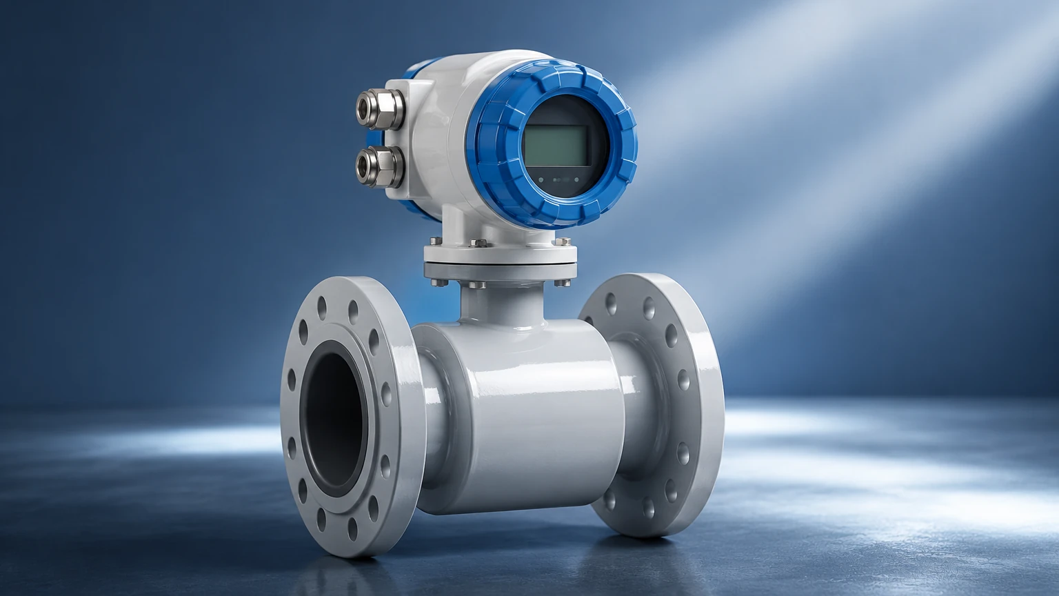
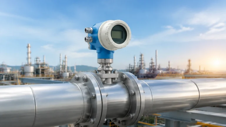
A standard electromagnetic flow meter consists of two primary assemblies: the flow sensor (installed in the pipeline) and the transmitter (the electronic unit that processes the signal).
1. Measuring Tube: Usually constructed from non-magnetic stainless steel to prevent interference with the magnetic field. It is lined with an insulating material to prevent the induced voltage from short-circuiting through the metal pipe.
2. Liner: A critical component that protects the tube from the process fluid and provides electrical insulation. Common materials include PTFE, PFA, and various rubbers.
3. Magnetic Coils: Located outside the measuring tube, these coils are energized by the transmitter to create a uniform magnetic field across the flow profile.
4. Electrodes: These are in direct contact with the fluid. They must be made of materials that resist corrosion and chemical attack from the specific media being measured.
5. Transmitter: The "brain" of the meter. It provides the excitation current to the coils, filters out noise, calculates the flow rate, and provides the user interface for calibration and diagnostics.
Practical Selection Criteria
Selecting the right electromagnetic flow meter requires a detailed analysis of the process conditions. Because the technology relies on electrical induction, the most critical requirement is that the fluid must have a minimum level of electrical conductivity, typically ≥ 5 μS/cm (microsiemens per centimeter). This excludes deionized water and most hydrocarbons (oils, fuels).
Liner Material Selection
The choice of liner depends on the temperature, pressure, and chemical properties of the fluid.
| Liner Material | Temperature Range | Typical Applications |
| :— | :— | :— |
| PTFE (Teflon) | -40°C to 180°C | Highly corrosive chemicals, acids, and bases. |
| PFA | -40°C to 200°C | Similar to PTFE but better for high-vacuum or high-pressure steam. |
| Neoprene / Hard Rubber | 0°C to 60°C | Water treatment, wastewater, and mildly abrasive slurries. |
| Polyurethane | -20°C to 60°C | Highly abrasive mining slurries and sand-water mixtures. |
Electrode Material Selection
Electrodes must be compatible with the fluid to prevent pitting or chemical degradation.
- Stainless Steel 316L: Suitable for water, wastewater, and mildly corrosive liquids.
- Hastelloy C: Used for aggressive chemicals and seawater.
- Titanium: Excellent for chloride-bearing liquids and certain acids.
- Tantalum: Reserved for highly aggressive acids like hydrochloric or sulfuric acid.
- Platinum-Iridium: Used for the most extreme chemical environments where other metals fail.
Installation Considerations
To achieve the specified accuracy (often ±0.5% of rate or better), an electromagnetic flow meter must be installed correctly. Improper installation is the leading cause of measurement errors in the field.
* Full Pipe Requirement: The meter must always be completely full of liquid. If the pipe is partially empty, the meter will read incorrectly (usually over-reading). Installing the meter in a vertical pipe with upward flow is the best way to ensure a full pipe.
* Straight Pipe Runs: While magmeters are less sensitive to flow disturbances than some other technologies, they still require straight pipe sections to stabilize the flow profile. A general rule is 5D (five times the pipe diameter) of straight pipe upstream and 2D downstream from the meter.
* Grounding: This is the most critical electrical requirement. The fluid, the sensor, and the transmitter must be at the same electrical potential. In plastic or lined pipes, grounding rings or grounding electrodes are necessary to provide a path for the reference signal and to eliminate stray electrical noise.
* Avoid Air Bubbles: Entrained air or gas bubbles can cause significant signal noise. Avoid installing the meter at the highest point of a piping system where air tends to collect.
Limitations and Constraints
While highly versatile, the electromagnetic flow meter is not a universal solution. Engineers must be aware of its limitations:
* Conductivity: As mentioned, it cannot measure non-conductive fluids like oil, grease, or pure alcohol.
* Vacuum Conditions: Certain liners, particularly PTFE, can collapse or be pulled away from the tube wall under high vacuum conditions unless specifically designed with mechanical anchors (like PFA with a metal mesh).
* Temperature Limits: The electronics and liner materials have upper temperature thresholds that must not be exceeded.
* Coating and Scaling: If the fluid leaves a non-conductive coating on the electrodes (such as fats or minerals), the signal will eventually be lost. In these cases, meters with electrode cleaning circuits or ultrasonic cleaning may be required.
Integration with Level Measurement
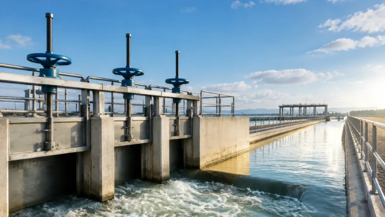
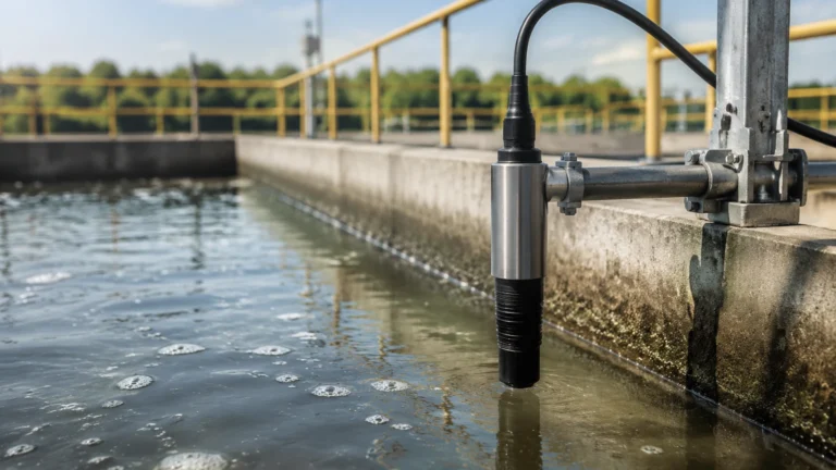
In many industrial applications, flow measurement is only one part of the equation. For comprehensive process control, flow data is often integrated with level measurement data from tanks and vessels. For instance, in a water treatment plant, an electromagnetic flow meter monitors the effluent rate while hydrostatic or radar level sensors monitor the basin levels. For professional-grade instrumentation and to explore a wide range of industrial sensors, you can visit the Welk Main Page to review product options and application support.
Frequently Asked Questions (FAQ)
Q: Can an electromagnetic flow meter measure the flow of steam or gas?
No. Gases and steam are not electrically conductive. For these applications, vortex or thermal mass flow meters are typically used.
Q: Does the viscosity of the liquid affect the accuracy?
Generally, no. Magmeters are independent of viscosity, density, and pressure, provided the flow remains within the meter's velocity range (typically 0.3 to 10 m/s).
Q: How often does a magmeter need calibration?
Because there are no moving parts to wear out, magmeters are very stable. However, many industries require annual or biennial verification to comply with environmental or quality standards. This can often be done using electronic verification tools without removing the meter from the line.
Q: What happens if the flow direction changes?
Most modern electromagnetic flow meters are bi-directional. They can measure flow in both directions and provide separate totals for forward and reverse flow via the transmitter settings.
Q: Are there minimum velocity requirements?
Yes. While magmeters can measure very low flows, accuracy typically degrades below 0.3 m/s (1 ft/s). It is often better to size the meter slightly smaller than the pipe size to increase the velocity through the sensor, provided the resulting pressure drop is acceptable.
Summary of Best Practices
To ensure the success of an electromagnetic flow meter installation, follow these steps:
1. Verify Conductivity: Ensure the fluid meets the minimum threshold.
2. Match Materials: Select liners and electrodes based on the chemical and thermal properties of the media.
3. Optimize Location: Choose a spot in the piping where the pipe remains full and the flow profile is stable.
4. Prioritize Grounding: Follow the manufacturer's grounding instructions strictly to prevent signal interference.
By adhering to these engineering principles, the electromagnetic flow meter provides a reliable, low-maintenance solution for liquid flow measurement across the water, chemical, and food industries.