Unguided Radar Level Transmitter
Unguided Radar Level Transmitter: A Technical Engineering Guide
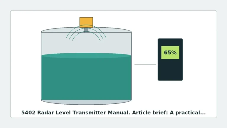
In the field of industrial process automation, the demand for non-contacting measurement solutions has grown significantly. Among these technologies, the unguided radar level transmitter stands out as a versatile and robust instrument capable of handling aggressive media, high temperatures, and varying pressures. Unlike guided wave radar (GWR), which uses a physical probe to direct the signal, unguided radar—often referred to as non-contacting radar—transmits electromagnetic pulses through the air space of a vessel.
This guide provides a comprehensive technical overview of unguided radar technology, its operating principles, selection criteria, and the critical installation factors that engineers and procurement specialists must consider to ensure reliable performance in B2B industrial environments.
Measurement Principles of Unguided Radar
To select the correct instrument, one must first understand how an unguided radar level transmitter interacts with the process medium. These devices operate on the principle of "Time of Flight" (ToF) using electromagnetic waves, typically in the microwave spectrum.
Pulse Radar vs. FMCW
There are two primary methods used by Radar Level Meters to determine distance:
1. Pulse Radar: The transmitter emits a short microwave pulse toward the product surface. The pulse is reflected back to the antenna, and the sensor measures the time elapsed between transmission and reception. Since the speed of light is constant, the distance is calculated as: `Distance = (Speed of Light × Time) / 2`.
2. FMCW (Frequency Modulated Continuous Wave): The transmitter emits a continuous signal with a constantly changing frequency. When the reflected signal is received, it is compared to the signal being emitted at that exact moment. The frequency difference is directly proportional to the distance. FMCW is generally preferred in modern industrial applications due to its higher accuracy and better signal-to-noise ratio.
The Role of the Dielectric Constant (εr)
The reflectivity of the microwave signal depends heavily on the dielectric constant (εr) of the medium. Materials with high dielectric constants, such as water (εr ≈ 80), reflect signals very strongly. Hydrocarbons, oils, and certain solids have low dielectric constants (εr < 2), which absorb more energy and return a weaker echo. When using an unguided radar level transmitter on low-dielectric media, the selection of the correct frequency and antenna type becomes critical to ensure the signal is not lost in the background noise.
Frequency Bands and Their Applications
The frequency at which an unguided radar operates determines its beam angle, sensitivity, and ability to penetrate steam or dust. Modern industrial radar typically falls into three categories:
* 6 GHz (C-Band): Known for its ability to penetrate heavy foam, steam, and turbulence. However, these units require very large antennas to maintain a narrow beam, making them less common in modern small-vessel applications.
* 26 GHz (K-Band): The long-standing industrial standard. It offers a balance between antenna size and signal focus. It is suitable for a wide range of liquids and some solids.
* 80 GHz (W-Band): The current state-of-the-art. Higher frequency allows for much smaller antennas and extremely narrow beam angles (as tight as 3°). This makes it ideal for tall, narrow tanks or vessels with internal obstructions like agitators or heating coils.
Selection Criteria for Industrial Applications
Choosing the right unguided radar level transmitter requires a detailed analysis of the process environment. The following table summarizes the primary selection factors for common industrial scenarios.
Table 1: Technical Selection Matrix
| Feature | 26 GHz Radar | 80 GHz Radar | Considerations |
| :— | :— | :— | :— |
| Beam Angle | 8° to 20° | 3° to 6° | Narrower beams avoid internal obstructions. |
| Measurement Range | Up to 30m (98 ft) | Up to 120m (393 ft) | 80 GHz is superior for deep silos or tall tanks. |
| Accuracy | ±3 mm to ±5 mm | ±1 mm | 80 GHz offers higher precision for custody transfer. |
| Foam Resistance | Moderate | Low | Lower frequencies penetrate foam better. |
| Dust/Steam | Good | Excellent | High-frequency signal processing handles dust better. |
| Nozzle Size | 50mm to 150mm | 20mm to 100mm | 80 GHz allows for smaller process connections. |
Installation Considerations and Constraints
Even the most advanced unguided radar level transmitter will fail if installed incorrectly. Because the signal propagates through the air in a cone shape, the physical layout of the tank must be respected.
1. Beam Angle and Obstructions
The "beam" is not a laser; it is a spread of energy. Any internal structure—such as ladders, pipes, or agitator blades—within the beam's path will create a "false echo." While modern software can perform "false echo suppression" (mapping out static reflections), it is best practice to install the sensor where the beam has a clear path to the product surface.
2. The Nozzle Effect
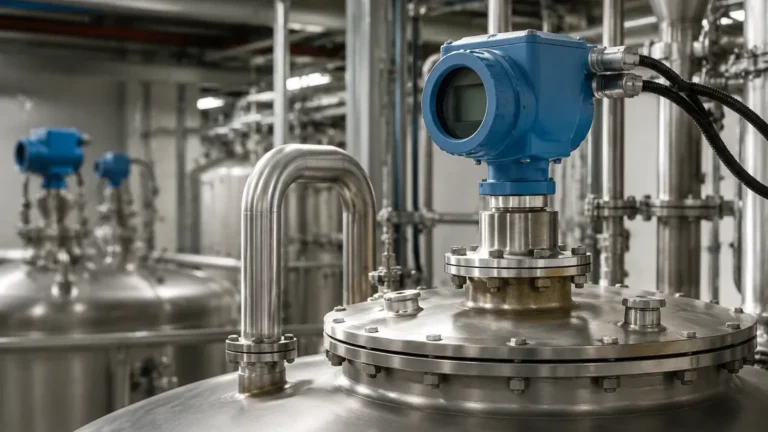
The nozzle (the pipe segment where the radar is mounted) can cause signal interference if it is too long or too narrow. Ideally, the antenna should extend slightly past the bottom of the nozzle to prevent internal reflections within the mounting pipe. If a long nozzle is unavoidable, a lens antenna or a specific high-frequency 80 GHz unit is recommended to minimize the "ringing" effect.
3. Minimum Distance (Dead Zone)
Every radar transmitter has a "blind zone" or "dead zone" directly beneath the antenna (typically 50mm to 200mm). If the liquid level enters this zone, the device cannot provide an accurate reading. Engineers must ensure the maximum expected fill level remains below this threshold.
4. Mounting Position
* Wall Distance: Never mount the radar in the center of a tank (unless it is a flat-roofed tank) or too close to the wall. Mounting too close to the wall (less than 200mm to 500mm depending on height) can cause signal degradation due to multiple reflections.
* Parabolic vs. Horn Antennas: Horn antennas are standard for most liquids. Parabolic antennas are used for long-range solids measurement where the signal needs to be focused over distances exceeding 50 meters.

Application Risks and Limitations
While unguided radar is highly reliable, it is not a universal solution. Certain process conditions present significant risks:
* Heavy Surface Foam: Thick, dense foam (like shaving cream) can absorb the radar signal entirely, resulting in a "Loss of Echo" (LOE) error. In these cases, a guided wave radar or a lower-frequency unguided unit may be required.
* Extremely Low Dielectric Media: For materials like liquid nitrogen or certain dry powders, the reflection may be too weak for a standard unguided radar. Specialized high-sensitivity electronics or GWR probes are often preferred here.
* Vacuum and Pressure: While the radar signal itself is unaffected by vacuum, the mechanical seal of the antenna must be rated for the process pressure. High-pressure applications often require specialized PTFE or ceramic seals.
FAQ for International Buyers and Engineers
Q: Can unguided radar measure through a plastic tank lid?
A: Yes. Since microwaves can penetrate non-conductive materials like plastics (PE, PP, PVC) and fiberglass, the transmitter can often be mounted outside the tank, looking through a plastic window or the tank roof itself, provided the material is not too thick or reinforced with metal.
Q: How does agitation affect the reading?
A: Surface turbulence caused by an agitator can scatter the radar signal. However, most modern Radar Level Meters utilize sophisticated algorithms to average the signal and provide a stable level reading despite the waves.
Q: Is calibration required on-site?
A: Unlike hydrostatic transmitters which require calibration against fluid density, unguided radar is pre-calibrated by the manufacturer based on distance. On-site commissioning usually involves setting the "Zero" (empty) and "Span" (full) points relative to the tank height.
Q: What is the maintenance requirement for these sensors?
A: Because there are no moving parts and no contact with the medium (if installed correctly), maintenance is minimal. In applications with heavy condensation or buildup, a periodic wipe of the antenna lens may be necessary, though many units now feature a "purge connection" to clean the antenna with compressed air automatically.
Conclusion
The unguided radar level transmitter is a cornerstone of modern industrial level measurement. By offering a non-contacting solution, it reduces the risk of sensor corrosion and mechanical failure, leading to lower total cost of ownership (TCO). When selecting a device, engineers must prioritize frequency selection (26 GHz vs. 80 GHz) based on the vessel geometry and the dielectric properties of the medium.
For professional-grade instrumentation tailored to water treatment, chemical processing, or oil and gas applications, Welk provides a range of high-performance solutions. To explore specific models and technical specifications, Review product options and application support to find the ideal configuration for your facility's requirements.