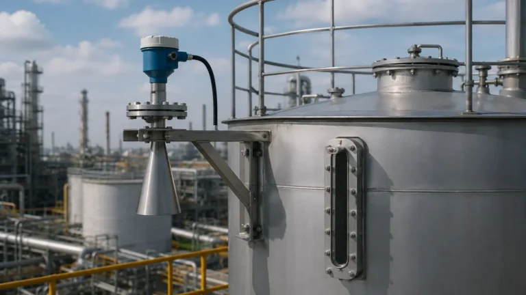
Rosemount 5408 Radar Level Transmitter Manual
Rosemount 5408 Radar Level Transmitter Manual: Engineering Selection and Installation Guide
In modern process automation, the accuracy and reliability of level measurement are critical for operational safety and efficiency. The Rosemount 5408 Radar Level Transmitter represents a significant advancement in non-contacting level measurement technology. This guide serves as a technical reference for engineers and procurement specialists, detailing the operating principles, selection criteria, and installation requirements essential for integrating Radar Level Meters into industrial environments.
1. Measurement Principle: FMCW Technology
To effectively utilize the Rosemount 5408 radar level transmitter manual, one must first understand the underlying technology. Unlike traditional pulse radar, which measures the time of flight of a single microwave pulse, the Rosemount 5408 utilizes Frequency Modulated Continuous Wave (FMCW) technology.
How FMCW Works
In an FMCW system, the transmitter emits a continuous electromagnetic signal with a frequency that varies linearly over time (a frequency ramp). The signal reflects off the surface of the medium and is received by the antenna. Because the transmitter is constantly changing its frequency, there is a distinct difference between the frequency currently being emitted and the frequency of the reflected signal that has just returned.
This frequency difference ($Δf$) is directly proportional to the time of flight ($t$). By analyzing this shift, the device calculates the distance to the product surface with high precision. The primary advantage of FMCW over pulse radar is its ability to provide a much higher signal-to-noise ratio, which is particularly beneficial in environments with turbulence, foam, or low-dielectric materials.
2. Key Features and Model Variants
The Rosemount 5408 is designed for versatility across various industries, including chemical processing, oil and gas, and power generation. The series is typically divided into two main functional categories:
* Rosemount 5408: The standard model for high-accuracy process level applications.
* Rosemount 5408:SIS: Specifically designed for Safety Instrumented Systems, certified to SIL 2 (IEC 61508) for use in overfill prevention and critical safety loops.
Technical Specification Overview
| Feature | Specification |
| :— | :— |
| Measurement Range | Up to 40 meters (131 ft) |
| Accuracy | ± 2 mm (0.08 in.) |
| Operating Pressure | Full vacuum to 100 bar (1450 psi) |
| Operating Temperature | -60°C to +250°C (-76°F to +482°F) |
| Output Protocol | 4-20 mA/HART, Foundation Fieldbus |
| Frequency | ~24 GHz (K-band) |
3. Antenna Selection and Application Engineering
Selecting the correct antenna is the most critical step in ensuring the performance of Radar Level Meters. The Rosemount 5408 manual identifies several antenna types tailored to specific process conditions.
Cone Antenna
The cone antenna is the most common choice for general-purpose applications. It is available in various sizes (typically 50 mm, 80 mm, and 100 mm). Larger cones provide a narrower beam width, which helps avoid internal tank obstructions such as agitators or heating coils.
Process Seal Antenna
For applications involving corrosive media or hygiene requirements, the process seal antenna uses a PTFE or PEEK face to isolate the transmitter electronics from the process. This design is ideal for the chemical and food & beverage industries where cleaning-in-place (CIP) or aggressive vapors are present.
Parabolic Antenna
The parabolic antenna is designed for long-range measurements (up to 40m) or for measuring solids and powders. Its unique shape provides a very narrow beam and high gain, allowing it to pick up weak reflections from uneven surfaces or low-dielectric materials.
4. Installation Guidelines and Constraints
Proper mechanical installation is vital to prevent signal interference. Engineers should adhere to the following constraints derived from standard industrial practices and the Rosemount 5408 radar level transmitter manual.
Nozzle Requirements
* Nozzle Height: The antenna should ideally extend below the nozzle. If the antenna is retracted inside a tall nozzle, internal reflections (ringing) can interfere with the signal near the top of the tank.
* Nozzle Diameter: Ensure the nozzle diameter is large enough to accommodate the selected antenna without contact.
Tank Placement
* The 1/10th Rule: Mount the transmitter at a distance from the tank wall that is at least 1/10th of the total tank height. This minimizes the risk of signal interference from wall reflections.
* Avoid the Center: Never mount a radar transmitter in the dead center of a domed tank. The curved roof can act as a parabolic reflector, concentrating unwanted noise and false echoes back to the sensor.
* Obstruction Clearance: Ensure the signal beam path is clear of ladders, pipes, and agitator blades. If obstructions are unavoidable, the Rosemount Radar Master Plus software can be used to "map out" these static reflections.
5. Configuration and Commissioning
Once installed, the Rosemount 5408 requires configuration via the HART protocol. The most efficient method is using the Rosemount Radar Master Plus software, which provides a graphical interface for echo curve analysis.
Essential Configuration Steps
1. Device Setup: Enter the tank height (reference point to zero level) and the calibration distance (reference point to full level).
2. Dielectric Constant ($εr$): Input the dielectric constant of the medium. If unknown, the 5408 has algorithms to track the surface, but accurate $εr$ values improve reliability in low-dielectric applications (e.g., hydrocarbons).
3. False Echo Suppression: Perform a "Learn Tank" or "Surface Trek" scan while the tank is empty or at a low level. This allows the transmitter to identify and ignore reflections from internal structures.
6. Application Risks and Limitations
While Radar Level Meters are highly robust, certain conditions can challenge their accuracy:
* Heavy Foam: While FMCW radar can penetrate some light foam, extremely dense or thick foam (like protein-based foam) may absorb the microwave signal entirely, leading to a loss of echo.
* Condensation and Buildup: Significant moisture or product buildup on the antenna face can attenuate the signal. In such cases, a process seal antenna or an antenna with a purging connection is recommended.
* Extreme Turbulence: Rapidly changing surface levels or heavy splashing can scatter the radar signal. The Rosemount 5408 addresses this through advanced signal processing and damping filters, but mechanical stilling wells may be required in extreme cases.
7. Maintenance and Troubleshooting
The Rosemount 5408 is a low-maintenance device due to its lack of moving parts. However, the manual suggests periodic verification of the following:
* Signal Quality Metrics: Monitor the Signal-to-Noise Ratio (SNR). A declining SNR over time may indicate antenna buildup or a failing seal.
* Diagnostic Alerts: The 5408 features Smart Meter Verification, which provides health monitoring of the electronics and antenna without interrupting the process.
Common Troubleshooting Scenarios
| Symptom | Potential Cause | Recommended Action |
| :— | :— | :— |
| Level jumps to 100% | Reflection from nozzle or top obstruction | Increase False Echo Suppression threshold |
| Signal lost at low levels | Poor reflection from tank bottom | Enable "Bottom Projection" mode in software |
| Erratic readings during filling | Turbulence or heavy dust | Increase damping time or use a stilling well |
8. Buyer’s Checklist for International Procurement
When sourcing industrial level measurement equipment, international buyers should confirm the following technical details to ensure compatibility and compliance:
1. Hazardous Area Certifications: Confirm if ATEX, IECEx, or FM approvals are required for the installation site.
2. Process Connection Standards: Specify flange types (ANSI, DIN, or JIS) and pressure ratings.
3. Material Traceability: Request MTRs (Material Test Reports) for wetted parts, especially for high-pressure or corrosive applications.
4. Software Compatibility: Ensure the site’s existing DCS or PLC supports HART 7 or the specific protocol version of the transmitter.
Conclusion
The Rosemount 5408 Radar Level Transmitter is a sophisticated tool that, when applied correctly, provides unparalleled accuracy in level measurement. By adhering to the engineering principles outlined in the Rosemount 5408 radar level transmitter manual—particularly regarding antenna selection and tank geometry—operators can ensure long-term reliability and safety in their process environments. For diverse industrial needs, exploring a wide range of Radar Level Meters allows for the selection of the most cost-effective and technically sound solution for any specific application.
Frequently Asked Questions (FAQ)
Q: Can the Rosemount 5408 measure the interface between two liquids?
A: While primarily designed for surface level, FMCW radar can sometimes detect interfaces if the upper liquid has a low dielectric constant and the lower liquid has a high one. However, guided wave radar is generally preferred for dedicated interface measurement.
Q: What is the minimum dielectric constant ($εr$) the 5408 can detect?
A: The Rosemount 5408 can typically detect materials with a dielectric constant as low as 1.2, provided the antenna is appropriately sized and the installation is optimized.
Q: Does the 5408 require periodic recalibration?
A: No, unlike hydrostatic transmitters, radar transmitters do not suffer from mechanical drift and generally do not require routine recalibration once the tank geometry is correctly mapped.
Download Rosemount 5408 Radar Level Transmitter Manual as a PDF