Non Intrusive Ultrasonic Flow Meter
Non Intrusive Ultrasonic Flow Meter
In modern industrial process control, the ability to measure fluid velocity without breaching the integrity of the piping system has become a critical requirement. The non intrusive ultrasonic flow meter, often referred to as a clamp-on ultrasonic flow meter, provides a versatile solution for monitoring liquid flow in applications ranging from municipal water treatment to complex chemical processing. By utilizing acoustic signals transmitted through the pipe wall, these instruments eliminate the need for pipe cutting, process downtime, and the risk of leaks associated with traditional inline meters.
As industries move toward more efficient maintenance and digital integration, understanding the technical nuances of non-intrusive measurement is essential for engineers and plant managers. This guide explores the fundamental principles, selection criteria, and installation best practices for ultrasonic flow measurement technology.
Measurement Principles of Ultrasonic Flow Meters
Non-intrusive ultrasonic flow meters operate based on one of two primary acoustic principles: Transit-Time or Doppler Effect. Selecting the correct principle depends entirely on the characteristics of the fluid being measured.
Transit-Time Method
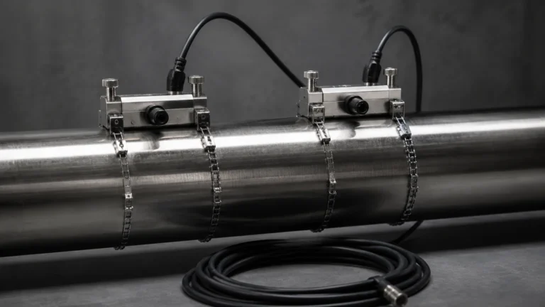
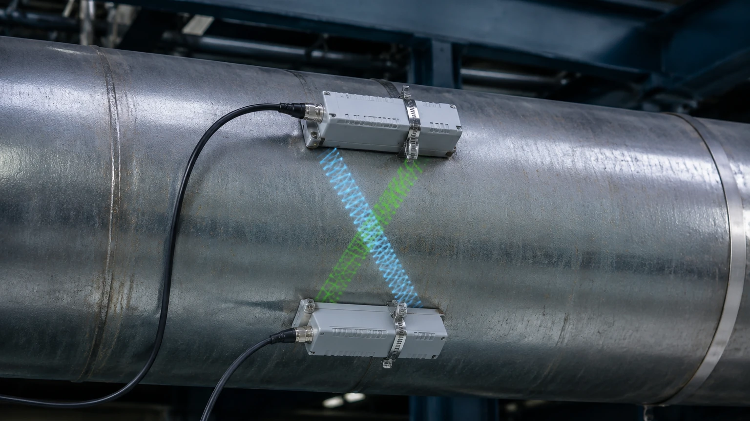
This is the most common method used for clean liquids. It employs a pair of transducers, each acting as both a transmitter and a receiver. The transducers are clamped to the outside of the pipe at a specific distance from each other.
One transducer sends a pulse of ultrasonic sound diagonally through the pipe wall and the liquid to the second transducer. The meter then reverses the process, sending a pulse from the second transducer back to the first. When the liquid is moving, the pulse traveling in the direction of the flow (downstream) moves faster than the pulse traveling against the flow (upstream). The difference in the time taken for these two pulses to travel the same distance is directly proportional to the velocity of the liquid. Once the velocity is determined, and the pipe’s cross-sectional area is known, the volumetric flow rate can be calculated.
Doppler Effect Method
The Doppler method is used for liquids containing suspended solids or entrained air bubbles. The meter transmits a continuous high-frequency sound signal into the liquid. These sound waves reflect off the particles or bubbles moving with the flow. Due to the motion of these reflectors, the frequency of the reflected signal is shifted (the Doppler shift). The flow meter measures this frequency shift to calculate the fluid velocity.
While transit-time meters require relatively clean fluids to ensure the signal can pass through the medium, Doppler meters require a minimum concentration of "reflectors" (typically at least 100 parts per million of particles larger than 100 microns) to function correctly.
Advantages of Non-Intrusive Technology
The shift toward non-intrusive measurement is driven by several operational and economic advantages over traditional electromagnetic or turbine meters.
1. Zero Process Interruption: Installation does not require shutting down the system or cutting into the pipe. This is particularly valuable in 24/7 operations like power plants or water distribution networks.
2. No Pressure Drop: Because there are no mechanical parts or probes protruding into the flow stream, the meter introduces zero hydraulic resistance, saving energy in pumping systems.
3. Chemical Compatibility: Since the sensors never touch the fluid, there is no risk of corrosion from aggressive chemicals or contamination of high-purity liquids (e.g., in pharmaceutical or semiconductor manufacturing).
4. Portability and Flexibility: Many non-intrusive units are available as handheld or portable kits, allowing engineers to verify the performance of existing inline meters or conduct temporary audits across different points in a facility.
5. Safety: In high-pressure or toxic fluid applications, maintaining the integrity of the pipe wall significantly reduces the risk of hazardous leaks during installation or maintenance.
For facilities looking to integrate these technologies into broader automation systems, it is helpful to Review product options and application support to ensure the chosen hardware aligns with existing industrial protocols.
Key Evaluation Criteria for Selection
Choosing a non intrusive ultrasonic flow meter requires a detailed assessment of the application environment. A mismatch between the instrument and the process conditions often leads to signal loss or inaccurate readings.
Pipe Material and Condition
Ultrasonic signals must pass through the pipe wall. Materials like carbon steel, stainless steel, PVC, and ductile iron are generally excellent conductors of sound. However, pipes with internal linings (such as cement, rubber, or glass) can be challenging if there is an air gap between the lining and the pipe wall, which reflects the signal. Furthermore, heavily corroded or scaled pipes can scatter the ultrasonic beam, requiring the use of specialized high-power transducers.
Fluid Properties
Temperature and viscosity play significant roles. High-temperature applications (above 150°C) require specialized transducers and mounting hardware. Viscosity affects the flow profile; at very high viscosities, the flow may become laminar, requiring the meter to apply different Reynolds number compensation factors to maintain accuracy.
Accuracy Requirements
Standard clamp-on meters typically offer an accuracy of ±1% to ±3% of the flow rate. If the application requires higher precision (e.g., custody transfer), specialized multi-path meters or calibrated inline ultrasonic units may be necessary.
Selection Table: Applications and Fluid Types
| Application Type | Recommended Technology | Fluid Characteristics | Typical Pipe Materials |
| :— | :— | :— | :— |
| Potable Water | Transit-Time | Clean, low solids | Steel, PVC, DI |
| Wastewater/Sludge | Doppler | High solids, aerated | Steel, Concrete-lined |
| Chemical Dosing | Transit-Time | Homogeneous, corrosive | PTFE, PVDF, Stainless |
| Cooling Water | Transit-Time | Clean to slightly dirty | Carbon Steel, Copper |
| Crude Oil | Transit-Time/Hybrid | Variable viscosity | Carbon Steel |
| Ultra-Pure Water | Transit-Time | No particulates | PFA, Stainless Steel |
Installation Considerations and Best Practices
The accuracy of a non intrusive ultrasonic flow meter is highly dependent on the quality of the installation. Even the most advanced meter will fail if the transducers are poorly mounted.
Straight Pipe Requirements
To ensure a stable and predictable flow profile, transducers should be installed on a straight section of pipe. The standard recommendation is at least 10 pipe diameters (10D) of straight run upstream and 5 pipe diameters (5D) downstream from any disturbance such as elbows, valves, or pumps. If a valve is partially closed upstream, the required straight run may increase to 20D or 30D.
Transducer Mounting Modes
Depending on the pipe size and fluid attenuation, three mounting configurations are typically used:
* V-Method: The signal traverses the pipe twice, reflecting off the opposite wall. This is the standard for pipes ranging from 25 mm to 400 mm.
* Z-Method: The transducers are placed on opposite sides of the pipe, and the signal traverses the pipe once. This is used for large pipes (above 400 mm) or where the fluid is highly attenuating.
* W-Method: The signal traverses the pipe four times. This is reserved for very small pipes (under 25 mm) to increase the transit time and improve resolution.
Coupling Compounds
Since air is a poor conductor of high-frequency sound, a coupling agent (grease, gel, or epoxy) must be applied between the transducer face and the pipe surface to eliminate air gaps. In permanent installations, solid coupling pads or specialized high-temperature greases are used to ensure long-term signal stability.
Limitations and Common Challenges
While highly effective, non-intrusive meters are not universal solutions. Engineers must be aware of the following limitations:
* Aeration and Bubbles: In transit-time meters, excessive air bubbles (usually >2% by volume) will scatter the ultrasonic signal, leading to a "signal loss" error.
* Pipe Wall Thickness: Accurate measurement requires precise knowledge of the pipe wall thickness. If the thickness is unknown or incorrectly entered into the flow computer, the calculated path length will be wrong, leading to linear errors in flow measurement.
* Signal Attenuation: Certain materials, such as fiberglass or plastic pipes with high filler content, can absorb ultrasonic energy, making it difficult to get a reliable reading on large diameters.
* Zero-Flow Drift: At very low velocities (below 0.1 m/s), electronic noise and thermal gradients can cause the meter to report a small flow when the fluid is actually stationary.
Maintenance and Troubleshooting
One of the primary benefits of the non intrusive ultrasonic flow meter is low maintenance, as there are no moving parts to wear out. However, periodic checks are necessary to ensure continued performance.
1. Couplant Inspection: In temporary setups using gel couplants, the gel may dry out over time. For permanent installations, check for signal strength degradation, which may indicate the need to re-apply couplant or tighten the mounting straps.
2. Signal Strength Monitoring: Most modern meters provide a "Signal Quality" or "Signal-to-Noise Ratio" (SNR) value. A drop in this value often indicates a change in fluid properties (increased aeration) or a buildup of scale on the inner pipe wall.
3. Electronic Calibration: While the transducers do not drift, the electronic transmitter should be checked annually to ensure the timing circuits remain within specification.
Frequently Asked Questions (FAQs)
Q: Can a non-intrusive meter measure flow in a partially full pipe?
A: No. Most ultrasonic flow meters require the pipe to be completely full to accurately calculate the cross-sectional area and ensure the acoustic path is consistent. For partially full pipes, a combination of ultrasonic level sensors and area-velocity methods is typically required.
Q: Does the pipe color or paint affect the measurement?
A: Standard paint usually does not interfere with the signal, provided it is well-bonded to the pipe. However, loose or flaking paint must be removed, and thick coatings (like heavy bitumen) may need to be sanded down to ensure the transducers make good acoustic contact.
Q: How does temperature affect the measurement?
A: Temperature changes the speed of sound in both the pipe material and the liquid. Most high-quality flow meters include temperature compensation algorithms and can even accept an input from a PT100 sensor to adjust calculations in real-time.
Q: What is the minimum pipe size for clamp-on meters?
A: Most manufacturers offer transducers for pipes as small as 10 mm to 15 mm, though the installation becomes more sensitive to transducer alignment at these sizes.
For more information on industrial measurement solutions and technical specifications, you can visit the Main Page for a comprehensive overview of available technologies.
Conclusion
The non intrusive ultrasonic flow meter represents a significant advancement in industrial instrumentation, offering a balance of accuracy, safety, and ease of use. By eliminating the traditional barriers to flow measurement—such as system downtime and mechanical wear—it allows for more frequent and flexible monitoring across diverse piping networks. When applied with a clear understanding of the fluid dynamics and pipe conditions involved, these meters provide a reliable foundation for process optimization and resource management in any modern industrial facility.