Radar Level Sensor 4 20ma
Radar Level Sensor 4-20mA: An Engineering Guide to Selection and Implementation
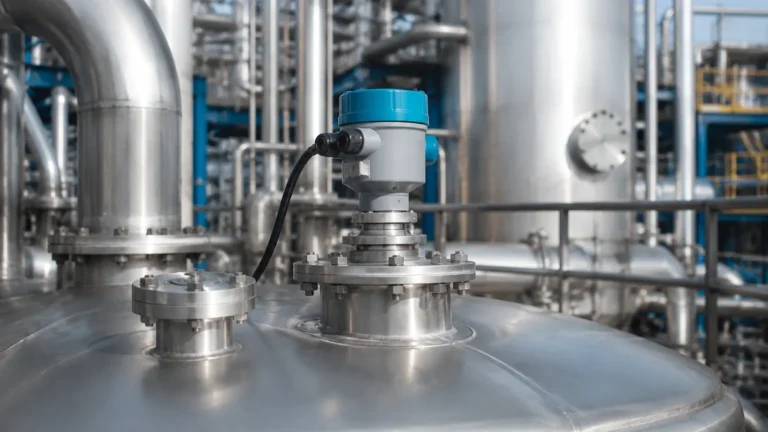
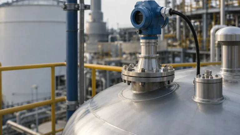
In the landscape of industrial process automation, the transition from mechanical level measurement to non-contact electronic sensing has been driven by the need for higher reliability and lower maintenance. Among these technologies, the radar level sensor 4-20ma has emerged as the definitive standard for continuous level monitoring in tanks, silos, and open channels. By combining microwave-based Time of Flight (ToF) measurement with the universally compatible 4-20mA analog output, these instruments provide a robust solution for challenging environments where temperature, pressure, and vapor would compromise other sensing methods.
For engineers and procurement specialists, understanding the nuances of Radar Level Meters is essential for ensuring process safety and operational efficiency. This guide examines the fundamental physics of radar measurement, the integration of the 4-20mA signal, and the critical factors involved in selecting the right equipment for industrial applications.
1. Measurement Principles: How Radar Sensors Work
Before selecting a specific radar level sensor 4-20ma, it is vital to understand the two primary methods used to calculate distance: Pulse Radar and Frequency Modulated Continuous Wave (FMCW).
Pulse Radar Technology
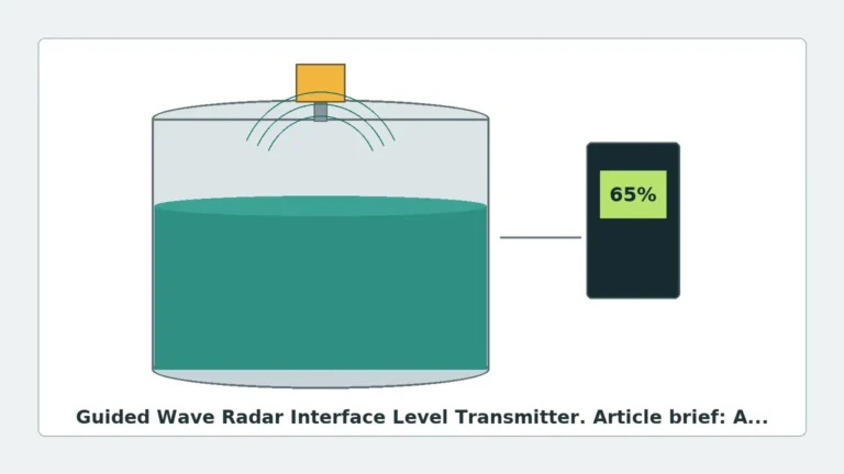
Pulse radar sensors emit short microwave pulses toward the surface of the medium. These pulses travel at the speed of light, reflect off the material surface, and return to the sensor's antenna. The instrument measures the "Time of Flight" (the interval between emission and reception) to calculate the distance.
* Formula: Distance = (Speed of Light × Time of Flight) / 2
* Advantage: Pulse radar typically consumes less power, making it suitable for two-wire loop-powered installations.
FMCW (Frequency Modulated Continuous Wave)
FMCW radar does not send discrete pulses; instead, it emits a continuous signal with a frequency that changes over time (a linear sweep). When the reflected signal is received, it is compared to the signal being emitted at that exact moment. The difference in frequency (the "beat frequency") is directly proportional to the distance.
* Advantage: FMCW offers significantly higher accuracy and a better signal-to-noise ratio, which is critical for measuring materials with low dielectric constants or in tanks with internal obstructions.
2. The 4-20mA Interface and HART Protocol
The "4-20mA" designation refers to the analog signaling standard used to communicate the level data to a PLC (Programmable Logic Controller) or DCS (Distributed Control System).
Why 4-20mA is Preferred
In an industrial setting, electrical noise is prevalent. A voltage-based signal (e.g., 0-10V) is susceptible to interference over long cable runs. However, a current loop maintains a constant current regardless of wire resistance or electromagnetic interference.
* 4mA: Typically represents the 0% level (empty tank).
* 20mA: Typically represents the 100% level (full tank).
* Fault Diagnostics: If the current drops to 0mA, the system immediately recognizes a wire break or power failure, a safety feature known as "live zero."
HART Communication
Most modern radar level sensor 4-20ma units also incorporate HART (Highway Addressable Remote Transducer) protocol. This allows digital data to be superimposed on the analog 4-20mA signal. Through HART, engineers can remotely access diagnostic data, change calibration settings, and monitor the internal temperature of the sensor without interrupting the primary analog level signal.
3. Technical Selection Criteria
Choosing the correct radar instrument requires an analysis of the material being measured and the physical constraints of the vessel. The following table summarizes the primary considerations for two common radar frequencies.
Selection Table: 26GHz vs. 80GHz Radar
| Feature | 26GHz Radar | 80GHz Radar |
| :— | :— | :— |
| Beam Angle | Wider (approx. 10° – 20°) | Narrow (approx. 3° – 8°) |
| Antenna Size | Larger (typically DN50-DN100) | Compact (as small as DN20) |
| Accuracy | ±3mm to ±5mm | ±1mm to ±2mm |
| Dust/Vapor Resistance | Good | Excellent |
| Application | Large tanks, simple geometries | Small tanks, narrow nozzles, agitators |
| Dielectric Constant | Requires εr > 1.9 | Can measure εr > 1.2 |
Dielectric Constant (εr)
The reflectivity of a material is determined by its dielectric constant. High-dielectric materials like water (εr ≈ 80) are easy to measure. Low-dielectric materials like plastic pellets (εr ≈ 1.5) or oils (εr ≈ 2.0) reflect very little energy. In these cases, a high-sensitivity FMCW radar level sensor 4-20ma is required to distinguish the weak reflection from background noise.
4. Installation Guidelines and Constraints
Even the most advanced radar level sensor 4-20ma will fail if installed incorrectly. Engineering teams must adhere to specific spatial constraints to ensure a clear signal path.
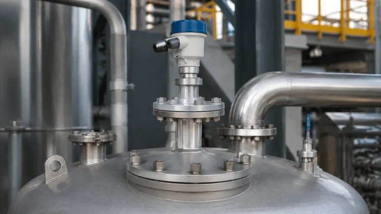
Nozzle Geometry
The mounting nozzle should be as short as possible. If the nozzle is too long or narrow, the radar signal may reflect off the internal walls of the pipe before it reaches the tank, creating a "false echo" near the top of the vessel. For 80GHz sensors, this is less of a concern due to the narrow beam, but for 26GHz units, the nozzle height-to-diameter ratio is critical.
The "One-Sixth" Rule
As a general rule of thumb, the sensor should be installed at a distance from the tank wall equal to approximately 1/6th of the tank diameter.
* Too close to the wall: The beam may interact with weld seams or scale buildup, causing interference.
* In the center: On domed-roof tanks, the center acts as a focal point for multiple reflections, which can lead to signal amplification and measurement errors.
Avoiding Internal Obstructions
Radar signals cannot "see through" metal. If the signal path is obstructed by heating coils, ladders, or agitator blades, the sensor will lock onto these fixed objects. While most software allows for "False Echo Suppression" (mapping out fixed reflections), it is best practice to install the sensor where it has a clear line of sight to the material surface.
5. Limitations and Application Risks
While Radar Level Meters are highly versatile, they are not universal solutions. Certain process conditions can attenuate the signal:
1. Heavy Foam: Dense, thick foam (like shaving cream) can absorb the radar signal entirely, preventing a return echo. In these cases, a guided wave radar or a mechanical float may be more appropriate.
2. Turbulent Surfaces: Rapidly boiling liquids or heavy agitation can scatter the radar signal. While software filtering can compensate for some turbulence, extreme cases may require a stilling well (a bypass pipe) to provide a calm surface for measurement.
3. Vacuum and Pressure: While the microwave signal itself is unaffected by vacuum or high pressure, the physical housing and seal of the sensor must be rated for the specific process pressure (e.g., PN16, PN40) and temperature.
6. Practical Maintenance and Troubleshooting
One of the primary benefits of a radar level sensor 4-20ma is the lack of moving parts, which significantly reduces maintenance requirements compared to ultrasonic or mechanical sensors. However, periodic checks are recommended:
* Antenna Buildup: In applications involving sticky liquids or heavy dust, the antenna face may accumulate material. While many radar sensors can "see through" a thin layer of buildup, heavy crystallization will eventually block the signal.
* Loop Testing: Periodically simulate a 4mA and 20mA signal from the sensor to verify that the PLC/DCS scaling matches the physical levels in the tank.
* Condensation: In high-humidity environments, water droplets can form on the antenna. Choosing a sensor with a PTFE (Teflon) lens or a drip-off design helps shed moisture and maintain signal integrity.
7. Frequently Asked Questions (FAQ)
Q: Can a radar level sensor 4-20ma measure through a plastic tank lid?
A: Yes. Since microwaves pass through non-conductive materials, radar can often measure the level inside a plastic or fiberglass tank without a hole being cut in the lid, provided the material is not too thick or reinforced with metal fibers.
Q: What is the difference between 2-wire and 4-wire radar sensors?
A: A 2-wire sensor uses the same pair of wires for both power and the 4-20mA signal (loop-powered). A 4-wire sensor has two wires for power (typically 24VDC or 110/220VAC) and two separate wires for the 4-20mA output. 4-wire units are generally used when higher power is needed for complex signal processing or heating elements.
Q: How does dust affect the radar signal?
A: Unlike ultrasonic sensors, which are easily blocked by dust, radar microwaves penetrate dust clouds with minimal attenuation. This makes radar the preferred choice for cement silos, grain elevators, and mining applications.
Conclusion
The radar level sensor 4-20ma represents the pinnacle of modern level measurement, offering a blend of precision, durability, and ease of integration. By selecting the appropriate frequency and ensuring a correct installation, industrial facilities can achieve maintenance-free level monitoring even in the most demanding environments. When sourcing these instruments, it is essential to provide the manufacturer with detailed process data—including the dielectric constant of the medium, the vessel dimensions, and the presence of any internal obstructions—to ensure the device is calibrated for optimal performance.