Thermowell in Pipe
Thermowell in Pipe
In industrial process control, the accurate measurement of temperature within a piping system is as critical as monitoring pressure or flow. However, placing a sensitive temperature element—such as a Resistance Temperature Detector (RTD) or a Thermocouple—directly into a high-velocity, high-pressure, or corrosive fluid stream poses significant risks to the instrument's integrity. To mitigate these risks, engineers employ a thermowell. This article provides a comprehensive technical guide to the application, selection, and installation of a thermowell in pipe systems, ensuring both measurement accuracy and mechanical safety.
Fundamental Principles of Thermowell Operation
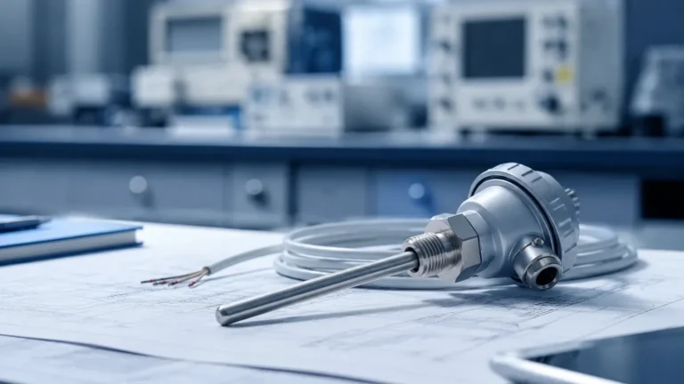
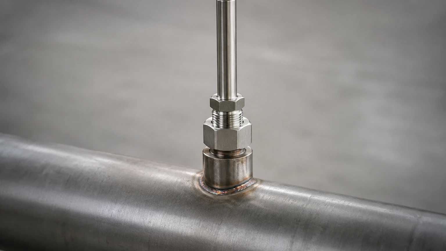
A thermowell is a cylindrical pressure-tight fitting used to protect temperature sensors installed in industrial processes. It acts as a physical barrier between the process media and the sensing element, while simultaneously serving as a heat exchanger.
Heat Transfer Mechanism
The measurement principle relies on thermal conduction. When a thermowell is inserted into a pipe, the process fluid transfers heat to the thermowell wall via convection. This heat then travels through the wall of the thermowell via conduction to the internal cavity where the sensor is housed. For an accurate reading, the sensor must be in physical contact with the bottom of the thermowell (the tip) to ensure it reaches thermal equilibrium with the process fluid.
Thermal Lag and Response Time
Because the thermowell adds mass and a secondary material layer between the fluid and the sensor, it introduces a "thermal lag." The time constant (the time required for the sensor to reach 63.2% of a step change in temperature) is higher for a sensor inside a thermowell than for a bare sensor. Engineers must balance the thickness of the thermowell wall—required for pressure resistance—against the need for a fast response time. Materials with high thermal conductivity and designs with tapered tips are often used to optimize this performance.
Installation Styles and Orientation
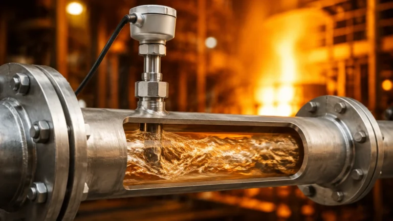
The placement of a thermowell in pipe sections requires careful consideration of fluid dynamics and mechanical stress. There are three primary orientations for installing a thermowell in a piping system:
1. Perpendicular Installation
In this configuration, the thermowell is installed at a 90-degree angle to the flow of the fluid. This is the most common installation method due to its simplicity. However, it subjects the thermowell to the maximum drag force and the highest risk of flow-induced vibration. It is typically recommended that the tip of the thermowell reaches the center third of the pipe diameter to ensure it is measuring the most representative temperature of the bulk fluid.
2. Elbow Installation
The thermowell is installed in a pipe elbow, with the tip pointing upstream (against the flow). This orientation is often preferred because it allows for a longer insertion length without obstructing the pipe's cross-section as severely as a perpendicular mount. It also places the sensing tip in a region of high turbulence, which enhances heat transfer and reduces response time.
3. Angled (Oblique) Installation
In smaller diameter pipes (typically under 100 mm), a perpendicular thermowell may not have sufficient insertion length to avoid "stem conduction error" (where heat escapes through the pipe wall, cooling the sensor). In these cases, the thermowell is installed at a 45-degree angle against the flow. This increases the submerged surface area of the thermowell, improving accuracy in narrow-bore piping.
Engineering Selection Criteria
Selecting the correct thermowell involves evaluating the process environment against mechanical standards. The following table outlines the primary selection factors for a thermowell in pipe applications:
| Feature | Options | Typical Application |
| :— | :— | :— |
| Stem Design | Straight, Tapered, Stepped | Tapered stems offer the best balance of strength and fast response time. |
| Connection Type | Threaded, Flanged, Socket Weld | Flanged is standard for high-pressure/hazardous chemicals; Threaded is used for low-pressure water/air. |
| Material | 316 Stainless Steel, Monel, Hastelloy, Inconel | 316SS is the industry standard; Hastelloy is used for highly corrosive acids. |
| Shank Length (U) | 50 mm to 1000+ mm | Must be long enough to reach the flow stream but short enough to avoid excessive vibration. |
| Lagging Extension (T) | 50 mm to 150 mm | Used in insulated pipes to allow the connection head to sit outside the insulation. |
Wake Frequency and Mechanical Integrity
One of the most critical aspects of designing a thermowell in pipe systems is the Wake Frequency Calculation (WFC). As fluid flows past a cylindrical thermowell, it creates alternating vortices known as Von Kármán vortices. These vortices exert a periodic force on the thermowell.
If the frequency of these vortices (the wake frequency) matches the natural frequency of the thermowell, resonance occurs. This can lead to catastrophic fatigue failure, where the thermowell snaps off and travels downstream, potentially damaging pumps, valves, or level measurement instruments.
In modern engineering, the ASME PTC 19.3 TW standard is the authoritative guide for these calculations. It evaluates:
* Static Stress: The pressure exerted by the fluid.
* Dynamic Stress: The vibration caused by vortex shedding.
* Pressure Limits: The external pressure rating of the thermowell at process temperature.
* Sensor Clearance: Ensuring the internal bore is sufficient for the sensor without compromising wall thickness.
If a thermowell fails the WFC, engineers must either shorten the insertion length, increase the root diameter, or use a "velocity collar" (though the latter is increasingly discouraged in favor of better geometry design).
Integration with Level Measurement Systems
While thermowells are temperature-specific components, they play a vital role in the broader field of industrial automation, particularly in level measurement. For many level measurement technologies, temperature data is a required input for compensation.
For instance, hydrostatic level transmitters measure the pressure exerted by a liquid column. Since the density of a liquid changes with temperature, an accurate temperature reading from a thermowell in a pipe or tank is necessary to convert pressure into a precise level height. Similarly, in high-accuracy radar level applications, temperature gradients in the vapor space can affect signal propagation speeds.
Manufacturers like Welk provide integrated solutions where temperature and level data work in tandem to provide a complete picture of vessel or pipeline status. For more information on how these instruments integrate into a complete process control loop, you can Review product options and application support on the Welk Main Page.
Installation Best Practices and Limitations
To ensure the longevity and accuracy of a thermowell in pipe, the following guidelines should be observed:
* Insertion Depth: As a rule of thumb, the insertion length (U) should be at least 10 times the diameter of the thermowell tip to minimize error from thermal conduction along the stem.
* Insulation: The pipe section and the lagging extension of the thermowell should be insulated. This prevents the ambient air temperature from influencing the sensor reading.
* Fluid Velocity: In high-velocity steam lines, always perform a wake frequency calculation. Tapered thermowells are generally safer in high-flow environments than straight-shank designs.
* Bore Fit: The clearance between the temperature sensor and the internal bore of the thermowell should be minimal. Large gaps act as insulators (air pockets), significantly slowing the response time.
Limitations
Thermowells are not suitable for every application. In highly viscous fluids or slurries, the thermowell can cause significant pressure drops or act as a point for material buildup (fouling). In these cases, non-intrusive surface-mount sensors or specialized "flush-mount" designs may be required, though they often sacrifice some accuracy compared to an immersion-style thermowell.
Frequently Asked Questions (FAQs)
Q: How often should a thermowell be inspected?
A: Inspection intervals depend on the corrosivity and abrasiveness of the process fluid. In high-velocity or corrosive service, an annual visual inspection for thinning walls or pitting is recommended. In benign services, they may last the life of the plant.
Q: Can I use a thermowell in a pipe smaller than 50 mm (2 inches)?
A: It is difficult to install a standard thermowell in very small pipes without severely restricting flow. Usually, the pipe is enlarged to a "tee" section of 80 mm or 100 mm at the point of measurement to accommodate the thermowell.
Q: What is the difference between a fabricated and a bar-stock thermowell?
A: A fabricated thermowell is made from a tube with a welded end-cap, suitable for low-pressure applications. A bar-stock thermowell is machined from a single solid piece of metal, providing much higher pressure ratings and better structural integrity for critical pipe flows.
Q: Does the orientation of the thermowell affect the reading?
A: Yes. Installing a thermowell pointing downstream (with the flow) can create a low-pressure zone at the tip, leading to localized temperature variations. Pointing the tip upstream or using a perpendicular mount is standard practice for accuracy.
By following these engineering principles for the selection and installation of a thermowell in pipe, facilities can ensure reliable temperature data while protecting their sensitive instrumentation from the harsh realities of industrial fluid dynamics.