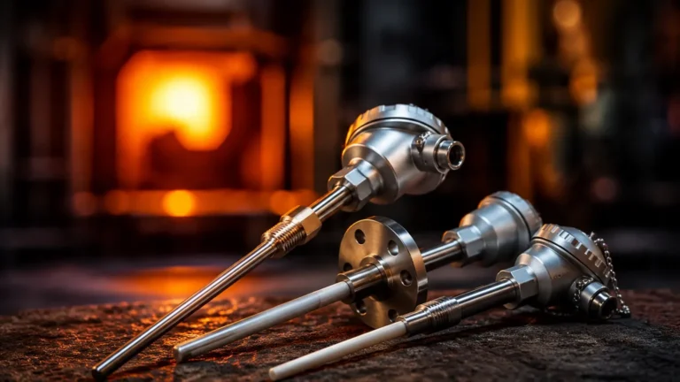
Flowfit Cua252
Flowfit Cua252
In industrial process automation and water treatment, the accuracy of analytical measurements depends not only on the sensor itself but also on the environment in which the measurement occurs. The Flowfit CUA252 is a specialized flow-through assembly designed to house optical sensors for turbidity and suspended solids measurement. By providing a controlled bypass or inline environment, this assembly ensures that sensors operate under optimal hydraulic conditions, minimizing errors caused by air bubbles, sediment buildup, or inconsistent flow rates.
For engineers managing complex liquid processing systems, integrating analytical assemblies like the CUA252 alongside robust level measurement hardware is essential for comprehensive process control. While analytical assemblies monitor fluid quality, reliable tank and vessel management requires precision instruments such as those found on the Welk Main Page.
Measurement Principles and Assembly Function
The Flowfit CUA252 is not a sensor in itself; rather, it is a process interface. To understand its importance, one must first understand the principles of optical turbidity measurement. Most sensors used within this assembly operate on the 90-degree scattered light principle (for low turbidity) or the four-beam scattered light principle (for high solids concentrations).
The Role of the Flow Cell
Optical sensors emit light into the medium and measure the light scattered by particles. For this measurement to be accurate, the following conditions must be met:
1. Elimination of Air Bubbles: Bubbles scatter light similarly to solid particles, leading to false high readings. The CUA252 is designed to facilitate bubble escape or to be used with an optional bubble trap.
2. Consistent Flow Geometry: The distance between the sensor head and the opposite wall of the assembly must be fixed and, in many cases, designed to absorb stray light (often through the use of dark material or specific geometries).
3. Representative Sampling: The assembly ensures that the fluid passing the sensor is a true representation of the process stream, preventing stagnant zones where solids might settle.
Technical Specifications and Selection Criteria
Choosing the correct version of the Flowfit CUA252 requires an evaluation of the process chemistry, temperature, and pressure. The assembly is typically available in various materials to suit different industrial environments.
Selection Table: Material and Application
| Feature | PVC (Polyvinyl Chloride) | PE (Polyethylene) | Stainless Steel (1.4404/316L) |
| :— | :— | :— | :— |
| Primary Application | Standard water treatment, cooling water | Corrosive chemical processes | High pressure, high temperature, food/pharma |
| Max. Temperature | 50°C (122°F) | 60°C (140°F) | 130°C (266°F) |
| Max. Pressure | 6 bar at 20°C (87 psi) | 6 bar at 20°C (87 psi) | 10 bar at 20°C (145 psi) |
| Chemical Resistance | Good for acids/bases | Excellent for aggressive media | Excellent for solvents and organics |
| Connection Types | Glue-in, Threaded, Flange | Welded, Threaded | Flange, Tri-Clamp, Threaded |
Key Evaluation Criteria
When specifying an assembly for a project, engineers should confirm the following:
* Flow Rate: The assembly typically requires a minimum flow rate (often around 100 L/h) to remain self-cleaning, but must not exceed a maximum velocity that could cause cavitation or sensor vibration.
* Cleaning Requirements: If the medium is prone to fouling (e.g., wastewater or lime milk), the assembly should be equipped with a spray cleaning nozzle or a chemical cleaning port.
* Optical Path Length: Ensure the assembly diameter is compatible with the sensor's calibration and the expected turbidity range.
Installation Considerations
Proper installation of the Flowfit CUA252 is critical to preventing measurement drift and mechanical failure. The following guidelines should be followed during the engineering phase.
Orientation and Positioning
The assembly should ideally be installed in a vertical bypass line with the flow direction from bottom to top. This orientation ensures that the assembly is always completely filled with liquid and allows any entrained air to rise naturally and exit the system rather than collecting on the sensor face.
If horizontal installation is unavoidable, the sensor should be mounted at a 45-degree angle from the top to prevent it from being covered by air pockets (at the top) or sediment (at the bottom).
Piping and Hydraulics
* Bypass Installation: Most CUA252 units are installed in a bypass to allow for sensor maintenance without shutting down the main process line. Isolation valves should be placed upstream and downstream.
* Pressure Reduction: If the main process line operates at a pressure exceeding the assembly's rating, a pressure reducer must be installed before the inlet.
* Drainage: A drain valve at the lowest point of the assembly or the bypass loop is recommended for manual cleaning and calibration checks.
Limitations and Common Risks
While the Flowfit CUA252 is a robust tool, it is subject to certain industrial limitations:
1. Fouling and Biofilm: In nutrient-rich water, biofilms can grow on the sensor windows inside the assembly. While the flow cell helps, it cannot entirely prevent biological growth. Automated cleaning systems are highly recommended in these scenarios.
2. Abrasive Media: In mining or heavy industrial applications, high concentrations of abrasive solids can erode the internal walls of PVC or PE assemblies. Stainless steel versions or ceramic-lined alternatives (if available) should be considered.
3. Light Interference: For very low turbidity measurements (e.g., drinking water), ambient light can penetrate plastic assemblies. In these cases, opaque materials or protective covers are necessary to maintain accuracy.
4. Condensation: In cold-water applications where the ambient air is warm and humid, condensation can form on the exterior of the assembly and eventually seep into sensor connections if they are not properly sealed (IP68).

Maintenance and Troubleshooting
Routine maintenance ensures the longevity of both the assembly and the housed sensor. A standard maintenance schedule should include:
* Monthly Visual Inspection: Check for leaks at the seals and O-rings. Inspect the outer housing for signs of chemical degradation or stress cracking.
* Sensor Calibration: While the sensor is housed in the CUA252, it should be removed periodically for a zero-point check in ultra-pure water and a slope check using a known standard (such as Formazin).
* Seal Replacement: O-rings (typically EPDM or Viton) should be replaced annually, especially if the assembly is frequently opened for manual cleaning.
Troubleshooting Table
| Symptom | Potential Cause | Recommended Action |
| :— | :— | :— |
| Unstable Readings | Air bubbles in the flow cell | Increase backpressure or install a bubble trap. |
| Slow Response Time | Flow rate too low | Check for blockages in the inlet or increase bypass flow. |
| Constant High Reading | Fouling on sensor face | Activate spray cleaning or manually clean the sensor. |
| Leaking at Sensor Port | Damaged O-ring or loose nut | Inspect and replace seals; tighten according to torque specs. |
Integration with Industrial Control Systems
The Flowfit CUA252 is a single component in a larger instrumentation strategy. For effective plant management, data from turbidity assemblies is often correlated with level measurement data. For example, in a sedimentation tank, the level of the sludge blanket and the turbidity of the effluent are both critical parameters.
Welk provides a comprehensive range of level measurement solutions, including radar and ultrasonic transmitters, which complement analytical assemblies by providing the necessary spatial context for the fluid being measured. To explore these options, visit the Main Page for detailed technical specifications on level sensing technology.
Frequently Asked Questions (FAQs)
Q: Can the Flowfit CUA252 be used for food and beverage applications?
A: Yes, provided the stainless steel version is selected and the seals meet FDA requirements. The assembly must be integrated into a CIP (Clean-In-Place) cycle to ensure hygiene.
Q: What is the maximum flow rate for the CUA252?
A: While it varies by model, typically the flow rate should be kept between 100 L/h and 400 L/h. Excessive flow can cause turbulence that interferes with optical measurements.
Q: How do I handle high-pressure applications?
A: For pressures exceeding 10 bar (145 psi), a standard CUA252 may not be suitable. In these cases, a high-pressure flow cell or a retractable assembly designed for direct pipe insertion is required.
Q: Does the assembly require a specific sensor brand?
A: The CUA252 is often designed with specific sensor dimensions in mind (typically 40mm diameter sensors). Always verify the mounting thread and immersion depth compatibility before purchase.
Q: How often should the spray cleaning nozzle be activated?
A: This depends entirely on the medium. In wastewater applications, a 10-second cleaning cycle every 2 to 4 hours is common. In cleaner water, once a day may suffice.
Summary for Project Engineering
When integrating the Flowfit CUA252 into a process design, engineers must look beyond the sensor and consider the hydraulic environment. By selecting the appropriate material, ensuring correct vertical orientation, and accounting for maintenance access, the assembly becomes a reliable link in the process control chain. For broader instrumentation needs, including the monitoring of tank volumes and chemical storage levels, professional solutions are available through the Welk Main Page, ensuring that both the quality and quantity of your process fluids are accurately managed.