Acoustic Flow Sensor
Acoustic Flow Sensor
In the landscape of industrial process control, the acoustic flow sensor has emerged as a cornerstone technology for non-invasive and high-precision fluid measurement. Utilizing ultrasonic sound waves to determine the velocity of a liquid or gas within a conduit, these sensors offer a unique combination of reliability and ease of maintenance. Unlike mechanical meters, an acoustic flow sensor has no moving parts to wear out or clog, making it an ideal choice for challenging environments ranging from municipal water treatment to aggressive chemical processing.
Understanding the engineering principles behind acoustic measurement is essential for selecting the right instrument. As a professional manufacturer, Welk emphasizes that the integration of flow and level measurement provides a holistic view of industrial automation systems. This guide explores the technical foundations, selection criteria, and practical installation requirements for acoustic flow sensors in modern B2B applications.
Measurement Principles of Acoustic Flow Sensors
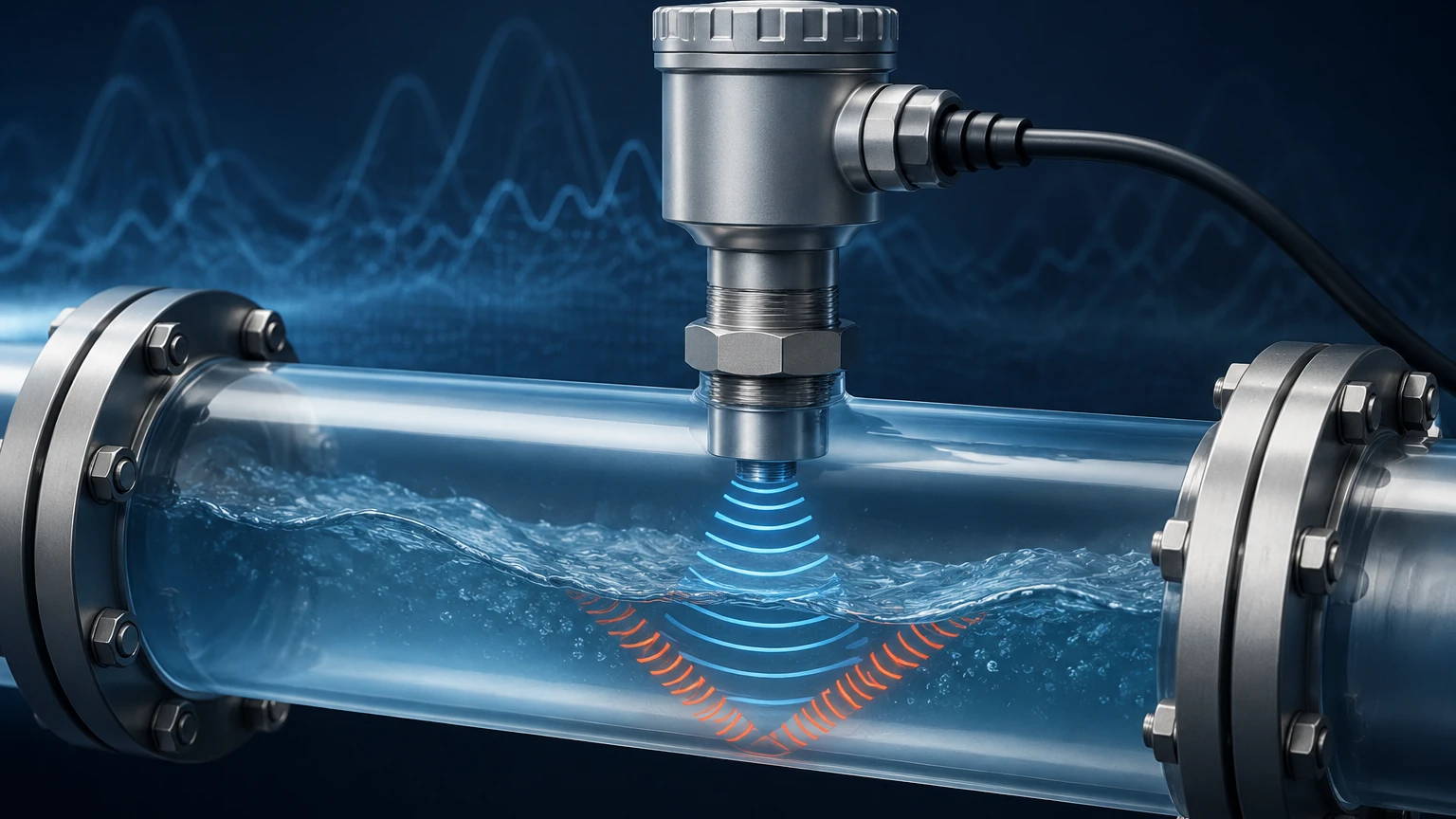
Acoustic flow sensors operate by transmitting high-frequency sound waves (typically above 20 kHz) through a fluid. The interaction between the sound waves and the moving fluid allows the sensor to calculate the flow rate. There are two primary physical principles used in these devices: Transit-Time and the Doppler Effect.
Transit-Time Principle
Transit-time sensors use a pair of transducers that function as both transmitters and receivers. They are mounted on opposite sides of a pipe, or in a specific configuration on the same side. The sensor measures the time it takes for an ultrasonic pulse to travel between the transducers in both directions.
When the fluid is stationary, the transit time in both directions is identical. However, when the fluid is moving, the pulse traveling with the flow (downstream) moves faster than the pulse traveling against the flow (upstream). The difference in these transit times ($Δt$) is directly proportional to the velocity of the fluid. By factoring in the cross-sectional area of the pipe, the device calculates the volumetric flow rate.
Doppler Effect Principle
The Doppler acoustic flow sensor operates by reflecting sound waves off moving discontinuities within the fluid, such as suspended solids, gas bubbles, or turbulence. When the transmitted sound wave hits a moving particle, its frequency shifts before being reflected back to the receiver. This frequency shift is proportional to the velocity of the particle, and by extension, the fluid itself. This method is particularly effective for "dirty" liquids where transit-time sensors might fail due to signal attenuation.
Transit-Time vs. Doppler Technology
Choosing between these two technologies depends entirely on the characteristics of the medium.
1. Transit-Time Sensors: These are best suited for clean liquids with less than 2% total suspended solids (TSS) or aeration. They are highly accurate and can measure flow in both directions. Common applications include potable water, deionized water, and light oils.
2. Doppler Sensors: These require at least 100 parts per million (ppm) of particles or bubbles larger than 100 microns to function correctly. They are the preferred solution for wastewater, slurries, and aerated liquids where a transit-time signal would be blocked.
For engineers looking to optimize their facility's measurement infrastructure, reviewing the comprehensive product options on the Main Page of our technical catalog can provide further insights into how these technologies are packaged for specific industrial needs.
Key Evaluation Criteria for Selection
Selecting an acoustic flow sensor requires a detailed analysis of the process environment. Engineers must consider the following factors to ensure long-term accuracy and performance.
Pipe Material and Condition
The acoustic properties of the pipe wall significantly impact signal transmission. While most metals (carbon steel, stainless steel, ductile iron) and plastics (PVC, PE, PVDF) are excellent conductors of sound, materials like concrete-lined pipes or heavily corroded iron pipes can present challenges. If the pipe has an internal liner, the material and thickness of that liner must be known to calibrate the sensor's signal processing algorithm.
Fluid Properties
Beyond the cleanliness of the fluid (which dictates the choice between Transit-Time and Doppler), temperature and viscosity are critical. Sound travels at different speeds depending on the temperature of the medium. High-quality sensors include temperature compensation features to maintain accuracy across fluctuating process conditions.
Flow Profile and Reynolds Number
Acoustic sensors calculate flow based on velocity. To convert velocity to volume accurately, the flow profile must be fully developed and predictable. This is determined by the Reynolds number. In laminar flow, the velocity profile is parabolic, while in turbulent flow, it is flatter. Modern digital acoustic flow sensors use sophisticated flow profile compensation to adjust for these variations.
Performance Comparison Table
| Feature | Transit-Time Sensor | Doppler Sensor |
| :— | :— | :— |
| Fluid Type | Clean liquids, low aeration | Slurries, aerated liquids, wastewater |
| Accuracy | 0.5% to 1.0% of reading | 1.0% to 2.0% of full scale |
| Installation | In-line or Clamp-on | Usually Clamp-on |
| Pipe Size Range | 15 mm to over 5000 mm | 25 mm to 3000 mm |
| Sensitivity to Solids | High (Signal may fail) | Low (Required for measurement) |
| Bidirectional Flow | Yes | Generally No |
Installation Guidelines and Best Practices
The performance of an acoustic flow sensor is often more dependent on the installation quality than the hardware itself. Following standardized engineering practices is vital.
Straight Pipe Requirements
To ensure a stable flow profile, sensors should be installed in a straight section of pipe. The general rule of thumb is the "10D and 5D" rule: the sensor requires a straight run of at least 10 pipe diameters upstream and 5 pipe diameters downstream from any elbows, valves, or pumps. If the upstream disturbance is a pump or a partially open valve, the requirement may increase to 20D or 30D.
Transducer Mounting Methods
For clamp-on acoustic flow sensors, there are three primary mounting configurations:
* V-Method: The sound wave traverses the pipe twice. This is the standard method for pipe diameters ranging from 25 mm to 400 mm.
* Z-Method: The transducers are mounted on opposite sides of the pipe, and the sound wave traverses the pipe once. This is used for large pipes (above 400 mm) or where the fluid is slightly attenuating.
* W-Method: The sound wave traverses the pipe four times. This is reserved for very small pipes (typically below 50 mm) to increase the transit time and improve resolution.
Coupling Compounds
For clamp-on sensors, there must be no air gap between the transducer face and the pipe wall. Acoustic coupling grease or permanent adhesive pads are used to facilitate the transfer of sound energy. In outdoor or high-temperature installations, the choice of couplant is critical to prevent drying out or degradation over time.
Limitations and Common Application Risks
While highly versatile, the acoustic flow sensor is not a universal solution. Engineers should be aware of the following risks:
1. Air Pockets: In horizontal pipes, air can collect at the top, and sediment can collect at the bottom. Transducers should always be mounted at the 3 o'clock and 9 o'clock positions (the sides) to avoid these interference zones.
2. Pipe Wall Scaling: Internal scale buildup effectively changes the pipe's internal diameter and can attenuate the signal. Regular diagnostic checks of signal strength can help identify this issue.
3. Acoustic Short-Circuiting: In some plastic pipes, the sound may travel through the pipe wall faster than through the fluid, leading to erroneous readings. This requires sensors with advanced signal filtering capabilities.
4. Extreme Temperatures: While the transducers can often withstand high temperatures, the electronics must be protected. Remote-mounted transmitters are recommended for processes exceeding 100°C.
Integration with Level Measurement Systems
In many B2B industrial applications, flow measurement is only one part of the equation. In open channel flow (such as flumes and weirs) or partially filled pipes, an acoustic flow sensor must be paired with a level measurement instrument. By measuring the head (level) of the liquid and applying a known formula for the channel geometry, the system can calculate the flow rate in non-pressurized environments.
Welk provides a wide range of level measurement solutions, including radar and ultrasonic level meters, which work in tandem with flow sensors to provide comprehensive data for SCADA and PLC systems. Accurate level data ensures that flow calculations remain valid even when pipe fill levels vary.
Frequently Asked Questions (FAQ)
Q: Can an acoustic flow sensor measure gas flow?
A: Yes, but gas flow measurement requires specialized high-frequency transducers and high-gain electronics because gases have much lower acoustic impedance than liquids. Transit-time technology is typically used for gas applications.
Q: How often does a clamp-on sensor need recalibration?
A: Because there is no mechanical wear, the sensor itself is very stable. However, it is recommended to verify the installation and signal strength annually, especially if the coupling compound might have degraded.
Q: Does the pipe pressure affect the flow measurement?
A: Generally, no. Acoustic sensors measure velocity, which is independent of pressure in liquids. However, in gas applications, pressure affects the density and the speed of sound, requiring compensation.
Q: What is the minimum flow velocity required?
A: Most modern sensors can detect velocities as low as 0.01 m/s, though accuracy is typically specified from 0.1 m/s to 12 m/s.
Conclusion
The acoustic flow sensor represents a significant advancement in industrial instrumentation, offering a non-intrusive, low-maintenance, and highly accurate method for monitoring fluid dynamics. By understanding the distinction between transit-time and Doppler principles, adhering to strict installation guidelines, and accounting for fluid characteristics, process engineers can implement robust measurement solutions that enhance operational efficiency. For those seeking to integrate these technologies into broader level and flow control strategies, exploring professional-grade instruments is the next logical step in optimizing plant performance.