Electrode Sensor
Electrode Sensor
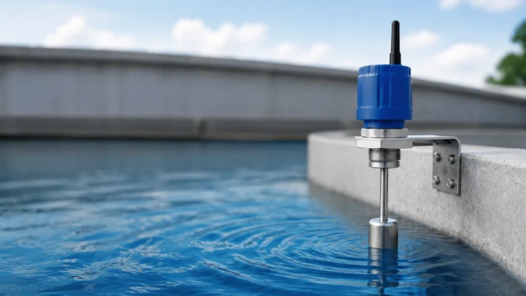
In the field of industrial process control, the electrode sensor—commonly referred to as a conductive level switch—represents one of the most reliable and cost-effective methods for point level detection in conductive liquids. Unlike continuous measurement technologies such as radar or ultrasonic sensors, the electrode sensor is designed to detect the presence or absence of a liquid at a specific height. This makes it an essential component for overfill protection, pump control, and dry-run prevention in industries ranging from water treatment to chemical processing.
As a professional manufacturer of industrial level measurement instruments, Welk provides a variety of level sensing solutions. Understanding the underlying physics and application constraints of the electrode sensor is critical for engineers and plant managers to ensure long-term operational stability. This guide provides a technical overview of electrode sensor technology, selection criteria, and installation best practices.
Measurement Principles of Electrode Sensors
The operation of an electrode sensor is based on the electrical conductivity of the process medium. The system typically consists of one or more metallic probes (electrodes) and a controller/relay unit.
The Conductive Circuit
When the liquid level rises and comes into contact with the electrode, an electrical circuit is completed between the electrode and a reference point. In metallic tanks, the tank wall itself often serves as the reference (ground). In non-metallic or plastic tanks, a separate "reference electrode" or "common electrode" must be installed to reach the lowest point of the tank.
Low-Voltage AC Operation
To prevent electrolysis—the chemical decomposition of the liquid or the erosion of the probes—modern electrode sensors use a low-voltage Alternating Current (AC) signal rather than Direct Current (DC). The controller measures the resistance between the sensing probe and the reference probe. When the resistance drops below a specific threshold (indicating the presence of a conductive liquid), the relay changes state, triggering an alarm or starting/stopping a pump.
Sensitivity Adjustment
Different liquids have different levels of conductivity. Deionized water has very low conductivity, while salt water or acids have very high conductivity. Most industrial electrode sensor controllers feature adjustable sensitivity, allowing the user to calibrate the device to distinguish between the actual liquid level and residual moisture or foam.
Key Components and Materials
An electrode sensor assembly is composed of three primary parts: the probe rods, the insulation, and the electrode holder.
1. Probe Rods: These are typically made from 304 or 316L stainless steel for general water applications. For highly corrosive environments involving acids or alkalis, specialized materials such as Hastelloy C, Titanium, or Monel are used.
2. Insulation: To prevent false triggering caused by splashing or condensation, the upper portion of the probes is often coated with insulating materials. Common choices include Polyolefin heat-shrink tubing, PVC, or PTFE (Teflon). PTFE is preferred for high-temperature or high-purity applications due to its chemical inertness.
3. Electrode Holder: This is the process connection that mounts the probes to the tank. It can be a threaded connection (e.g., G1", 1.5" NPT) or a flange. The holder must provide high electrical insulation between the individual probes and between the probes and the tank mounting.
Selection Criteria and Technical Specifications
Choosing the right electrode sensor requires an analysis of the liquid properties and the physical environment of the tank. The following table provides a general selection guide based on common industrial media.
Selection Table: Electrode Materials and Applications
| Media Type | Recommended Probe Material | Insulation Material | Typical Application |
| :— | :— | :— | :— |
| Potable Water | 304 / 316 Stainless Steel | Polyolefin / PVC | Storage tanks, building services |
| Wastewater / Sewage | 316L Stainless Steel | Heat-shrink Polyolefin | Sump pits, treatment plants |
| Dilute Acids | Hastelloy C / Titanium | PTFE | Chemical dosing, pickling lines |
| High-Temp Steam | 316L Stainless Steel | Ceramic / PTFE | Boiler level control |
| Deionized Water | 316L (High Sensitivity) | PTFE | Semiconductor, Pharma |
Physical Constraints
* Probe Length: Standard rod electrodes are usually available in lengths up to 3 meters (3000 mm). For deeper reservoirs or wells, suspended cable electrodes are used, where a weighted stainless steel probe is hung by a chemical-resistant cable.
* Pressure and Temperature: Standard electrode holders are typically rated for atmospheric pressure or low-pressure systems (up to 10 bar). High-pressure versions with ceramic seals are required for boiler applications. Temperature limits are generally dictated by the insulation and holder material, often ranging from -20°C to +150°C.
Installation Considerations for Industrial Environments
Proper installation is paramount to the accuracy of an electrode sensor. Failure to follow engineering guidelines often leads to "ghost" switching or failure to detect the level.
1. Tank Material and Grounding
In a metal tank, the tank wall is the most effective reference. A ground wire should be connected from the electrode holder to the tank shell. In plastic, fiberglass (FRP), or lined tanks, a reference probe must be installed. This probe must be longer than the longest sensing probe to ensure it remains in contact with the liquid at all times.
2. Preventing Bridge Circuits
If the liquid is prone to splashing or creates a thick foam, a "bridge" of liquid may form between two probes or between a probe and the tank wall. This creates a false conductive path. To prevent this:
* Ensure probes are spaced at least 20mm to 50mm apart.
* Use insulated probes where only the bottom 10mm to 20mm of the tip is exposed.
* Install the sensor away from the tank inlet where turbulence and splashing are highest.
3. Turbulence and Still Wells
In tanks with high agitation or fast-flowing inlets, the probes may sway or the liquid surface may be too unstable for a clean reading. In such cases, the electrode sensor should be installed inside a "still well" (a vertical pipe with vent holes). The still well acts as a mechanical damper, providing a calm surface for the probes.
4. Horizontal vs. Vertical Mounting
While electrode sensors are almost always mounted vertically from the top of the tank, short probes can be mounted horizontally through the side of a vessel for point detection. However, vertical mounting is preferred to prevent sediment from settling on the probes and causing a short circuit.
Limitations and Prohibitions
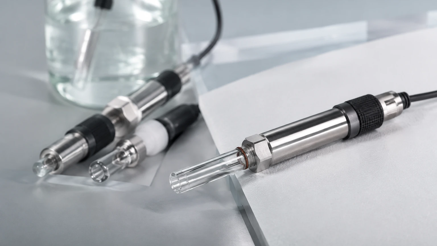
While highly versatile, the electrode sensor is not a universal solution. Engineers must be aware of the following limitations:
* Non-Conductive Liquids: Electrode sensors cannot detect oils, diesel, pure hydrocarbons, or distilled water with extremely low conductivity (typically < 5 μS/cm). For these media, Main Page technologies like ultrasonic or radar sensors are more appropriate.
* Coating and Scaling: If the liquid leaves a conductive residue or scale (such as calcium deposits in hard water or thick sludge), the sensor may stay "on" even after the liquid level drops. Regular cleaning or the use of vibration-based level switches may be necessary in these environments.
* Explosive Atmospheres: In hazardous areas (Ex zones), electrode sensors must be used in conjunction with intrinsically safe barriers to limit the energy available for ignition.
Maintenance and Troubleshooting
One of the primary advantages of the electrode sensor is its lack of moving parts, which significantly reduces maintenance requirements compared to float switches. However, periodic checks are recommended:
1. Probe Cleaning: In wastewater or chemical applications, inspect the probes every 6 to 12 months for build-up. Clean with a wire brush or appropriate solvent.
2. Insulation Integrity: Check the insulation for cracks or signs of chemical degradation. Damaged insulation can lead to false signals if condensation forms on the probe.
3. Controller Testing: Most controllers have a manual test button or can be tested by temporarily shorting the probe terminal to the ground terminal with a jumper wire to ensure the relay trips.
Frequently Asked Questions (FAQ)
Q: Can I cut the electrode rods to size on-site?
A: Yes, most stainless steel rod electrodes can be cut to the desired length during installation. Ensure that any insulation is stripped back at the tip (approximately 10-20 mm) to allow for electrical contact with the liquid.
Q: What is the maximum distance between the sensor and the controller?
A: This depends on the cable's capacitance and the sensitivity of the controller. Generally, a distance of up to 100 meters is acceptable using standard shielded signal cable. For longer distances, the sensitivity may need to be reduced to account for cable capacitance.
Q: Can electrode sensors be used for foam detection?
A: Yes. Because foam is often less conductive than the bulk liquid, an electrode sensor can be calibrated to detect the foam layer specifically, which is useful in fermentation or chemical mixing processes.
Q: How do I handle liquids that are highly turbulent?
A: Use a still well or a perforated bypass pipe. This stabilizes the liquid level around the probes and prevents mechanical stress on the rods.
Conclusion
The electrode sensor remains a fundamental tool in industrial level measurement due to its simplicity, durability, and low cost of ownership. By understanding the conductivity requirements of the media and ensuring proper installation—particularly regarding grounding and insulation—plant operators can achieve highly reliable point level control. For complex applications involving non-conductive fluids or the need for continuous level monitoring, it is advisable to consult a professional manufacturer to explore alternative technologies such as radar or ultrasonic transmitters. For more information on various level measurement technologies and to find the right fit for your project, visit the Main Page for comprehensive product specifications and application support.