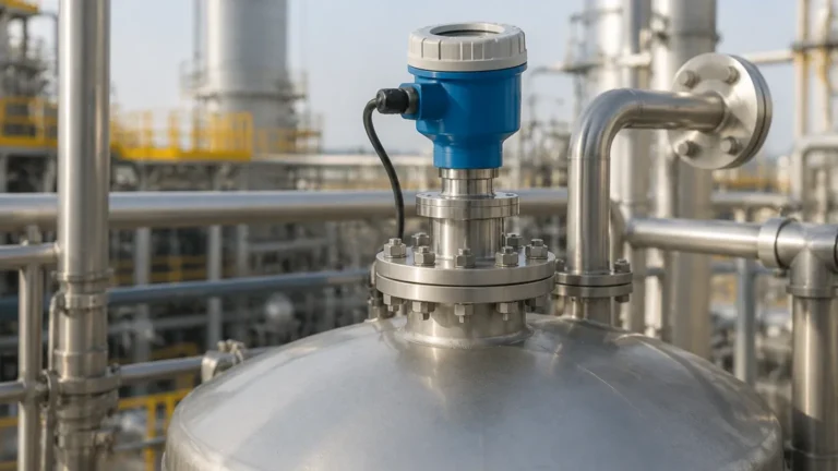
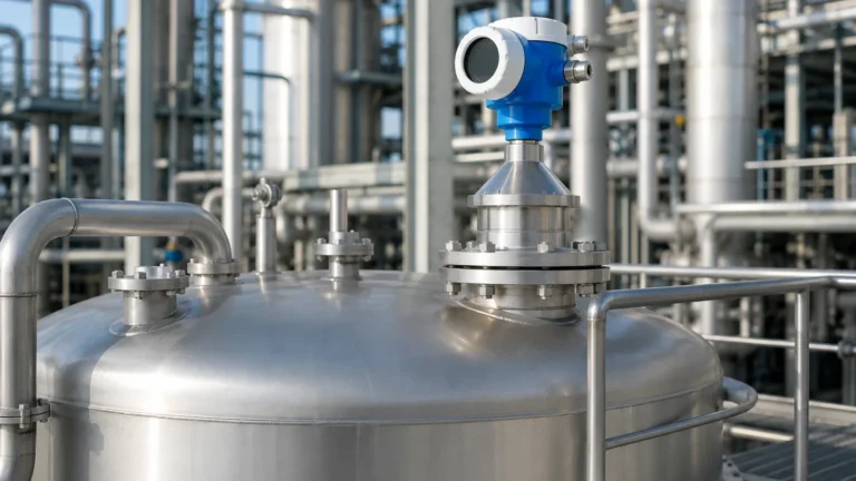
5300 Radar Level Transmitter
5300 Radar Level Transmitter: A Technical Guide to Guided Wave Radar Selection and Application
In the landscape of industrial process control, the accuracy of level measurement directly impacts safety, efficiency, and product quality. Among the various technologies available, the 5300 radar level transmitter represents a sophisticated implementation of Guided Wave Radar (GWR) technology. Designed for challenging applications involving liquids, slurries, and solids, this instrument provides high-performance measurement even under extreme temperature and pressure conditions.
This guide explores the fundamental principles of the 5300 series, provides engineering criteria for probe selection, and outlines critical installation parameters for international procurement and maintenance teams.
Understanding the Measurement Principle: Guided Wave Radar (GWR)
Before selecting a Radar Level Meters solution, it is essential to understand the underlying physics of the technology. The 5300 radar level transmitter operates on the principle of Time Domain Reflectometry (TDR).
The TDR Process
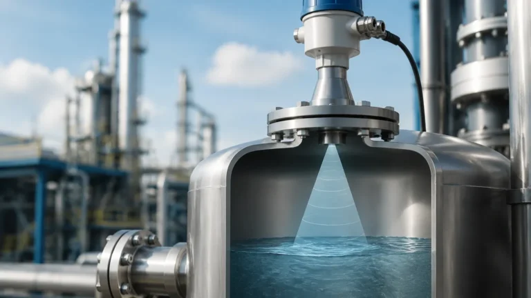
Unlike non-contact radar, which emits electromagnetic waves through the air, a GWR transmitter guides low-power microwave pulses along a physical probe (the waveguide).
1. Pulse Emission: The transmitter electronics generate a high-frequency microwave pulse that travels down the probe at the speed of light.
2. Reflection: When the pulse reaches the surface of the process medium, a portion of the microwave energy is reflected back toward the transmitter. This occurs because of the difference in the dielectric constant (εr) between the upper medium (usually air or vapor) and the process material.
3. Signal Processing: The instrument measures the time-of-flight between the pulse emission and the reception of the reflected signal.
4. Distance Calculation: Using the formula *Distance = (Speed of Light × Time) / 2*, the device determines the level. Since the speed of light is constant, the measurement is highly stable and independent of changes in pressure, temperature, or vapor space composition.
Direct Switch Technology
Modern iterations of the 5300 radar level transmitter often utilize "Direct Switch Technology." This enhancement increases the signal strength and reduces noise, allowing the device to measure materials with very low dielectric constants or across longer distances than traditional GWR units. This makes it particularly effective for hydrocarbon applications where the dielectric constant may be as low as 1.4.
Technical Specifications and Probe Selection
Selecting the correct probe is the most critical decision when specifying a 5300 radar level transmitter. The probe acts as the interface between the electronics and the process.
Probe Type Comparison
| Probe Type | Recommended Application | Max Range (Typical) | Minimum Dielectric (εr) |
| :— | :— | :— | :— |
| Single Lead (Rigid/Cable) | Viscous liquids, slurries, and coating materials. Best for dirty environments. | 60 m (197 ft) | > 10 (Direct) / > 1.4 (with TBF) |
| Twin Lead (Rigid/Cable) | Long-range measurements in clean liquids with moderate dielectric constants. | 50 m (164 ft) | > 1.9 |
| Coaxial | High-precision measurement in low-dielectric fluids, turbulent surfaces, or near internal obstructions. | 6 m (20 ft) | > 1.4 |
Material Considerations
Probes are typically manufactured from 316L stainless steel, but for corrosive environments, materials such as Hastelloy C-276, Monel, or PTFE-coated probes are available. Engineering teams must verify chemical compatibility using standard corrosion tables before final specification.
Engineering Selection Criteria
When evaluating the 5300 radar level transmitter for a specific project, consider the following technical factors:
1. Dielectric Constant (εr)
The dielectric constant of the medium determines the strength of the reflection. Water has a high dielectric (~80), providing a very strong signal. In contrast, oil-based products have low dielectrics (~2), requiring more sensitive electronics and specific probe types (like coaxial) to ensure a reliable echo.
2. Interface Measurement
One of the primary advantages of the 5300 series is the ability to measure both the total level and the interface level (e.g., oil over water). For successful interface measurement, the upper medium must have a lower dielectric constant than the lower medium, and the upper layer must be thick enough (typically >100 mm) for the transmitter to distinguish between the two reflections.
3. Process Conditions
* Pressure: Standard models handle up to 40 bar (580 psi), while high-pressure versions can exceed 345 bar (5000 psi).
* Temperature: Operating ranges typically span from -196°C (-320°F) for cryogenic applications to +400°C (+752°F) for power plant steam drums.
Installation Guidelines and Constraints
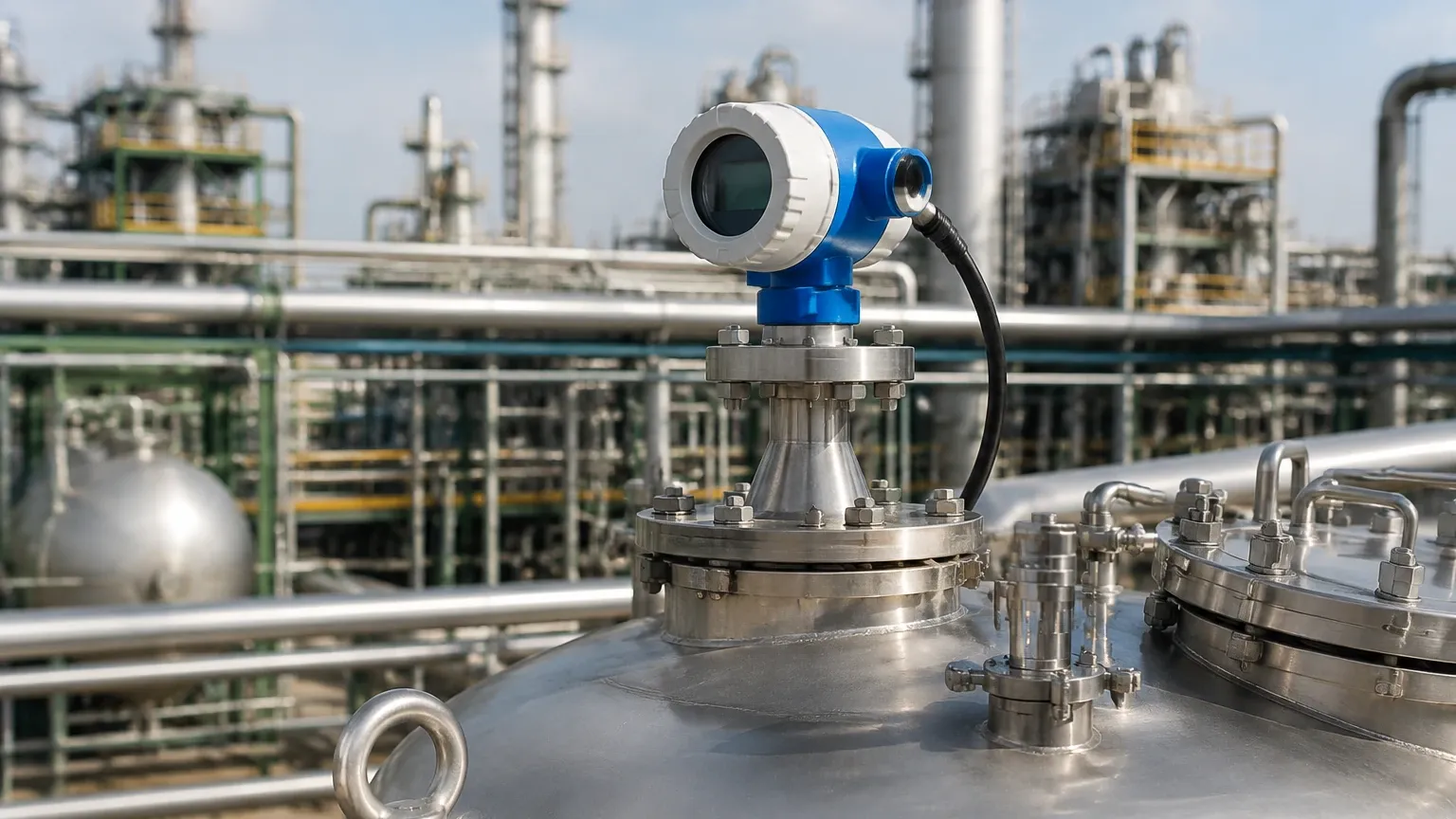
Proper installation is paramount to preventing signal interference and ensuring long-term reliability of Radar Level Meters.
Nozzle and Mounting
* Nozzle Diameter: The nozzle should be as wide and as short as possible. For single-lead probes, a 2-inch (50mm) or 3-inch (80mm) nozzle is standard. If the nozzle is too narrow or too long, it can create "ringing" or parasitic reflections that mask the true level signal.
* Obstructions: GWR probes have a "detection zone" around them. Any metal object (ladders, pipes, agitators) within this zone can cause false reflections. Single-lead probes require at least 300 mm (12 inches) of clearance from tank walls or internal structures.
Probe Anchoring
In tall tanks or vessels with high agitation, cable probes must be anchored to the bottom. However, the anchor must be designed to allow for thermal expansion of the probe to prevent mechanical stress on the transmitter housing.
Upper and Lower Dead Zones
Every 5300 radar level transmitter has a "dead zone" or "transition zone" at the top and bottom of the probe. In these areas, the measurement accuracy is reduced or lost entirely.
* Upper Dead Zone: Usually 100 mm to 500 mm depending on the probe and dielectric.
* Lower Dead Zone: Often 50 mm to 150 mm.
Engineers must account for these zones when calculating the effective measuring range of the vessel.
Application Risks and Limitations
While the 5300 radar level transmitter is highly versatile, certain conditions present risks to measurement integrity:
1. Heavy Coating and Bridging: While GWR handles thin coatings well, heavy, conductive buildup between a twin-lead probe or inside a coaxial probe can cause the signal to short-circuit, leading to a "stuck" high-level reading.
2. Emulsion Layers: In interface applications, a thick emulsion layer (rag layer) can scatter the microwave signal, making it difficult for the device to identify a distinct interface reflection.
3. Extremely Low Dielectrics: If the εr is below 1.4, the reflection may be too weak to detect. In these cases, a "Tank Bottom Forward" (TBF) tracking algorithm may be used, which infers the level based on the shift in the reflection from the tank bottom.
Maintenance and Troubleshooting
The 5300 series is generally low-maintenance due to the lack of moving parts. However, the following practices are recommended:
* Signal Quality Monitoring: Most 5300 transmitters provide a signal-to-noise ratio or signal strength metric. Monitoring this via HART or Foundation Fieldbus can provide early warning of probe coating or vessel scaling.
* Verification: Periodic verification using a secondary manual measurement (like a dip tape) is recommended for safety-critical loops (SIL 2/3).
* Echo Curving: Use the manufacturer's software to view the "echo curve." This visual representation of the reflections helps technicians identify and "mask" false echoes caused by internal tank structures.
Frequently Asked Questions (FAQ)
Q: Can the 5300 radar level transmitter be used in vacuum conditions?
A: Yes. Because GWR does not rely on air as a medium for the signal, it is unaffected by vacuum, unlike ultrasonic sensors.
Q: How does foam affect the measurement?
A: It depends on the foam density. Light, airy foam is usually transparent to the radar pulse. Dense, conductive foam may reflect the signal, causing the transmitter to read the top of the foam layer instead of the liquid level.
Q: Is it possible to shorten the probe in the field?
A: Most cable probes can be shortened in the field. Rigid probes can also be cut, but this requires recalibration of the electronics to account for the new probe length and the removal of the factory-defined end-of-probe reflection.
Conclusion
The 5300 radar level transmitter is a robust solution for complex industrial level challenges, offering superior performance in high-pressure and low-dielectric applications. By understanding the TDR principle and carefully selecting the probe geometry based on the process medium, engineers can achieve highly accurate and maintenance-free level monitoring. For those seeking comprehensive options in level technology, exploring the full range of Radar Level Meters ensures that the specific requirements of the process—whether it involves turbulence, foam, or extreme temperatures—are met with the appropriate technical configuration.