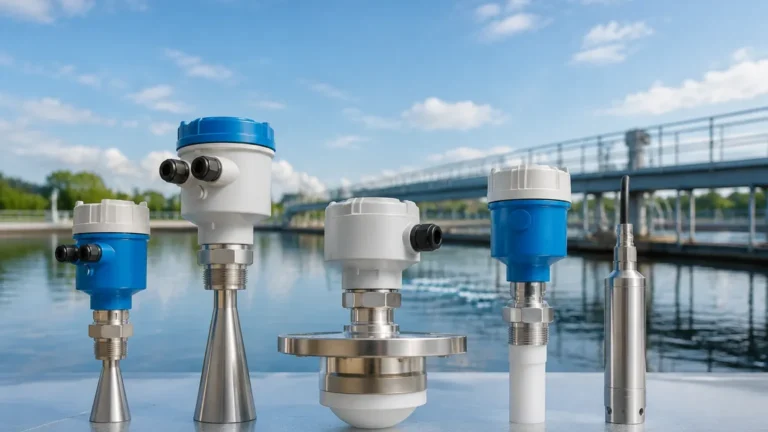
Flowline Ultrasonic Level Sensor
Flowline Ultrasonic Level Sensor
In the landscape of industrial automation and fluid management, the requirement for precise, non-contact level measurement has led to the widespread adoption of ultrasonic technology. A flowline ultrasonic level sensor represents a critical component in process control, offering a balance of reliability, ease of installation, and cost-effectiveness. These sensors are designed to provide continuous level measurement for a variety of liquids, ranging from clean water to corrosive chemicals, without physically touching the medium.
This article serves as a technical reference for engineers and plant managers, detailing the operational principles, selection criteria, and installation best practices for ultrasonic level sensing technology. By understanding the underlying physics and the environmental factors that influence performance, stakeholders can make informed decisions when visiting the Main Page to select appropriate instrumentation for their specific applications.
Measurement Principles of Ultrasonic Sensors
Ultrasonic level measurement is based on the "Time-of-Flight" (ToF) principle. The sensor, typically mounted at the top of a tank or vessel, contains a piezoelectric transducer that converts electrical energy into mechanical sound pulses.
The Time-of-Flight Calculation
The transducer emits a high-frequency sound pulse—usually in the range of 20 kHz to 200 kHz—which travels through the air space toward the surface of the liquid. When the pulse hits the surface, it is reflected back to the sensor as an echo. The sensor’s internal electronics measure the time interval between the emission of the pulse and the reception of the echo.
The distance from the sensor to the liquid surface is calculated using the formula:
D = (c × t) / 2
Where:
* D is the distance to the liquid surface.
* c is the speed of sound in the medium (typically air).
* t is the total time elapsed for the pulse to travel to the surface and back.
Since the total distance the pulse travels is twice the distance to the surface, the result is divided by two. Once the distance (D) is known, the sensor subtracts this value from the total tank height (H) to determine the actual level (L) of the liquid.
Temperature Compensation
The speed of sound (c) is not constant; it varies significantly with the temperature of the air through which it travels. In air, the speed of sound increases by approximately 0.6 meters per second for every degree Celsius increase in temperature. To maintain accuracy, a flowline ultrasonic level sensor must incorporate an internal temperature sensor to provide real-time compensation for these fluctuations. Without compensation, a 10°C change in temperature could result in a measurement error of nearly 1.7%.
The Blanking Zone (Dead Band)
Every ultrasonic sensor has a "blanking zone" or "dead band" immediately below the transducer face. This is a short distance where the sensor cannot accurately process a return signal because the transducer is still vibrating from the initial pulse emission. If the liquid level enters this zone, the sensor will report an error or provide an erratic reading. Typical blanking zones range from 10 cm to 50 cm (approx. 4 to 20 inches), depending on the frequency and power of the transducer.
Key Evaluation Criteria for Selection
Selecting the right flowline ultrasonic level sensor requires a thorough analysis of the application environment. Not all sensors are suitable for every liquid or tank geometry.
1. Measurement Range
The range of the sensor is determined by the frequency of the transducer. Higher frequency sensors (e.g., 80 kHz) are more compact and have smaller blanking zones but have a shorter effective range (up to 3 or 5 meters). Lower frequency sensors (e.g., 40 kHz) can penetrate further, reaching distances of 10 to 15 meters, but require larger transducers and have larger blanking zones.
2. Chemical Compatibility
The housing and transducer face material must be compatible with the liquid being measured. For water and general-purpose applications, Polycarbonate or Polypropylene (PP) is often sufficient. However, for corrosive acids or bases, Polyvinylidene Fluoride (PVDF) or PTFE-faced sensors are required to prevent chemical degradation of the instrument.
3. Output Signals and Integration
Industrial sensors typically offer several output options for integration into PLC (Programmable Logic Controller) or SCADA systems:
* 4-20 mA Analog: The industry standard for continuous level monitoring.
* HART Protocol: Allows for digital communication over the analog loop for diagnostics and configuration.
* Modbus RTU (RS485): Enables multi-drop networking and high-speed digital data transfer.
* Switch Outputs: Some sensors include integrated relays for high/low-level alarms.
4. Beam Angle
The beam angle refers to the width of the ultrasonic pulse as it spreads from the transducer. A narrower beam angle (e.g., 8 degrees) is preferable for tall, narrow tanks or tanks with internal obstructions like ladders, agitators, or pipes. A wider beam may cause "false echoes" if the pulse reflects off the tank wall or internal structures.
Technical Selection Table
| Feature | General Purpose Water | Chemical Storage | Long Range / Large Silo |
| :— | :— | :— | :— |
| Typical Range | 0.1m – 5m | 0.2m – 8m | 0.5m – 15m |
| Housing Material | Polycarbonate / ABS | PVDF / PTFE | Reinforced Plastic / SS |
| Operating Temp | -20°C to 60°C | -40°C to 80°C | -40°C to 90°C |
| Pressure Limit | Atmospheric | Up to 3 bar (43 psi) | Up to 2 bar (29 psi) |
| Accuracy | ±0.25% of range | ±0.2% of range | ±0.2% of range |
| Output | 4-20mA | 4-20mA + HART | Modbus / RS485 |
Installation Considerations and Best Practices
Correct installation is the most significant factor in ensuring the long-term reliability of a flowline ultrasonic level sensor. Even the most advanced sensor will fail if positioned incorrectly.
Positioning the Sensor
1. Avoid the Center: In cylindrical tanks with domed tops, do not mount the sensor in the exact center. The dome can act as a parabolic reflector, concentrating noise and multiple reflections back to the transducer.
2. Perpendicular Alignment: The sensor face must be perfectly parallel to the liquid surface. If the sensor is tilted, the pulse will reflect away from the transducer, resulting in a "Loss of Echo" (LOE) error.
3. Clear Path: Ensure there are no obstructions (pipes, ladders, or inflow streams) within the sensor’s beam angle. The path to the liquid must be clear.
4. Distance from Wall: The sensor should be mounted at least 20 cm to 30 cm away from the tank wall to prevent side-wall reflections.
Use of Stilling Wells and Standpipes
In applications where the liquid surface is turbulent or covered in foam, a stilling well (a vertical pipe submerged in the liquid) can be used. The sensor is mounted at the top of the pipe. The pipe acts as a guide for the ultrasonic pulse and provides a calm surface for measurement, effectively filtering out surface agitation.
Mounting in Standpipes
If the sensor must be mounted on a nozzle or standpipe to keep it out of the blanking zone, the inner diameter of the pipe must be smooth. Any burrs or weld seams inside the pipe can create false echoes. The pipe should be as short as possible, and the sensor face should ideally extend slightly past the bottom of the nozzle.

Limitations and Common Risks
While ultrasonic sensors are versatile, they have physical limitations that engineers must account for during the design phase.
* Foam: Heavy, dense foam is the primary enemy of ultrasonic sensors. Foam absorbs the sound pulse rather than reflecting it. If foam is expected, a radar level meter or a hydrostatic transmitter may be a better choice.
* Vacuum and Pressure: Ultrasonic waves require air or gas to travel. In a vacuum, the sensor cannot function. High-pressure environments change the density of the air, which significantly alters the speed of sound beyond what standard temperature compensation can handle.
* Heavy Vapor and Dust: Dense vapors (like those from concentrated nitric acid) or heavy dust can attenuate the signal, reducing the effective range of the sensor.
* Turbulence: Extreme surface turbulence can scatter the ultrasonic pulse. While software algorithms can filter some of this out, severe cases require stilling wells.
Practical Applications
Water and Wastewater Treatment
Flowline ultrasonic level sensors are widely used in pump lift stations, wet wells, and open channel flow measurement. In open channels, the sensor measures the head (height) of the water behind a flume or weir, and the electronics convert that height into a flow rate (e.g., liters per second).
Chemical Processing
Because the sensor does not touch the liquid, it is ideal for measuring aggressive chemicals like sodium hypochlorite, sulfuric acid, and various solvents. Using PVDF-housed sensors ensures that the instrument is not consumed by the vapors of the process.
Industrial Automation
In manufacturing, these sensors monitor the levels of lubricants, inks, and cooling water in small to medium-sized tanks. Their compact size and digital output make them easy to interface with modern IoT gateways and automation controllers.
Frequently Asked Questions (FAQ)
Q: How do I handle a "Loss of Echo" (LOE) alarm?
A: First, check the alignment of the sensor to ensure it is perpendicular to the liquid. Next, check for obstructions in the beam path or the presence of heavy foam. If the tank is empty and the sensor is mounted too high, it may be hitting the tank bottom at an angle that prevents a return signal.
Q: Can ultrasonic sensors be used for solids?
A: Yes, but with caution. Solids (like grain or plastic pellets) do not have a flat surface; they form cones. This scatters the signal. For solids, a sensor with a higher power output and a lower frequency is usually required, and the effective range is typically reduced by 50% compared to liquids.
Q: Does humidity affect the measurement?
A: Humidity has a very minor effect on the speed of sound—much less than temperature. In most industrial applications, the effect of humidity is negligible and does not require additional compensation.
Q: What is the lifespan of an ultrasonic transducer?
A: In clean environments, a high-quality transducer can last 10 years or more. However, in applications with high vibration or extreme temperature cycling, the piezoelectric crystal may degrade over time, leading to a weaker signal.
Conclusion
The flowline ultrasonic level sensor remains a cornerstone of industrial level measurement due to its non-contact nature and adaptability. By carefully considering the tank geometry, chemical environment, and potential physical obstructions, engineers can implement a solution that provides years of maintenance-free service. For those looking to explore specific models, technical datasheets, or customized OEM/ODM options, the Main Page provides a comprehensive starting point for selecting high-performance level measurement instrumentation.