Thermal Flow Meters
Thermal Flow Meters
In the landscape of industrial process control, the accurate measurement of gas flow is critical for operational efficiency, safety, and regulatory compliance. Thermal flow meters, specifically thermal mass flow meters (TMFMs), have emerged as a preferred technology for monitoring gas flows due to their ability to measure mass flow directly without the need for additional pressure or temperature compensation.
As industrial automation becomes more sophisticated, engineers and plant managers must understand the underlying physics and application constraints of these instruments. This guide provides a comprehensive technical overview of thermal flow meters, their selection criteria, and best practices for installation in diverse industrial environments.
Understanding the Measurement Principles of Thermal Mass Flow
Thermal flow meters operate based on the principle of thermal dispersion or convective heat transfer. The fundamental concept is that a fluid (typically a gas) moving past a heated surface will carry away heat. The rate of heat loss is directly proportional to the mass flow rate of the fluid.
The Sensor Configuration
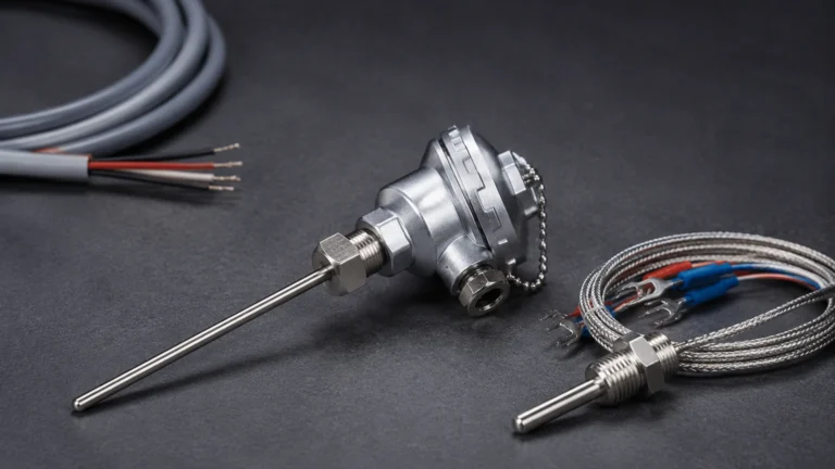
Most industrial thermal flow meters utilize two Resistance Temperature Detectors (RTDs) as sensors. These sensors are typically constructed of platinum and are protected within robust metal thermowells.
1. Velocity Sensor (Heated Sensor): This sensor is actively heated by an electrical circuit. It is designed to be the "hot" element in the process stream.
2. Reference Sensor: This sensor is unheated and measures the actual temperature of the process gas. It provides a baseline for the electronics to maintain a specific temperature differential.
Theoretical Basis: King’s Law
The operation is often described by King’s Law, which relates the heat loss from a wire to the fluid velocity. In practical terms, as gas molecules pass the heated sensor, they absorb heat. The amount of heat absorbed depends on the mass of the gas (its density and velocity) and its thermal properties (specific heat). Because the meter responds to the molecular cooling effect, it provides a mass flow reading (e.g., kg/h or Nm³/h) rather than a volumetric reading (e.g., m³/h), which would change with pressure and temperature fluctuations.
Key Technologies: Constant Temperature vs. Constant Power
Manufacturers like Welk implement thermal measurement through two primary electronic control methods. Each has specific advantages depending on the application requirements.
Constant Temperature Differential
In this mode, the electronics maintain a constant temperature difference (ΔT) between the heated velocity sensor and the reference sensor (typically around 30°C to 50°C). As the flow rate increases, more heat is dissipated, and the circuit must provide more electrical power to maintain the ΔT. This power consumption is the signal that is converted into a mass flow measurement.
* Advantages: Excellent sensitivity at low flow rates and a very fast response time to flow changes.
Constant Power
In constant power mode, a fixed amount of electrical energy is supplied to the heated sensor. The temperature difference (ΔT) between the heated sensor and the reference sensor is then measured. At high flow rates, the ΔT decreases as more heat is carried away; at low flow rates, the ΔT increases.
* Advantages: Generally more robust in high-temperature applications, though it may have a slower response time compared to constant temperature designs.
Industrial Applications and Gas Compatibility
Thermal flow meters are primarily used for gas applications. Because the measurement relies on the specific heat of the gas, the instrument must be calibrated for the specific gas or gas mixture present in the process. Common applications include:
* Compressed Air Management: Monitoring air leakage and optimizing compressor efficiency.
* Wastewater Treatment: Measuring aeration air flow and digester gas (biogas) production.
* Natural Gas Monitoring: Sub-metering for boilers, furnaces, and industrial heaters.
* Flare Gas Measurement: Handling low-pressure, low-velocity gas flows in refineries.
* Semiconductor Manufacturing: Precise delivery of high-purity process gases.
For facilities requiring a broad range of instrumentation beyond flow, including radar or ultrasonic sensors, consulting a professional manufacturer's Main Page can provide insights into integrated level and flow solutions.
Selection Criteria and Performance Specifications
When selecting thermal flow meters, engineers must evaluate several technical parameters to ensure the device is fit for purpose. Unlike differential pressure meters, thermal meters offer high turndown ratios (often 100:1 or better), allowing for accurate measurement across a wide range of flow conditions.
Practical Selection Table
| Parameter | Specification Range (Typical) | Considerations |
| :— | :— | :— |
| Accuracy | ±1% of reading + 0.5% of full scale | Depends on gas calibration and flow profile. |
| Repeatability | ±0.2% of full scale | Critical for process consistency. |
| Turndown Ratio | 100:1 to 1000:1 | Superior for detecting leaks or low-flow states. |
| Pressure Rating | Up to 70 bar (7 MPa) | Higher pressures require specialized sensor housings. |
| Temperature Range | -40°C to +250°C | High-temp versions available for stack gases. |
| Response Time | < 1 second | Crucial for control loops and safety shut-offs. |
| Pipe Sizes | DN15 to DN6000+ | Insertion styles are used for large ducts/pipes. |
Gas Composition and Calibration
Since the heat transfer rate varies by gas type, a meter calibrated for Air will not be accurate for Hydrogen or Carbon Dioxide. If the gas composition is variable (e.g., biogas with fluctuating methane/CO2 ratios), the accuracy of a standard thermal flow meter will degrade. In such cases, specialized gas-mix calibrations or redundant analytical sensors may be required.

Installation Guidelines for Optimal Accuracy
Proper installation is the most significant factor in achieving the rated accuracy of thermal flow meters. The goal is to ensure a fully developed, symmetrical flow profile at the point of measurement.
Straight Pipe Requirements
Turbulence caused by elbows, valves, and reducers can create swirls and velocity profile distortions. Standard recommendations include:
* Upstream: Minimum of 10 to 20 diameters (D) of straight pipe after a single elbow.
* Downstream: Minimum of 5 diameters (D) of straight pipe before any obstruction.
* Flow Conditioners: If the required straight runs are unavailable, flow conditioners (perforated plates or vane-type) can be used to shorten the necessary distances.
Orientation and Positioning
For horizontal pipes, the sensor should ideally be installed at the "2 o'clock" or "10 o'clock" position. This prevents the sensor from being submerged in moisture/condensate (at the bottom) or being trapped in a pocket of air or sediment (at the top). In vertical pipes, flow should ideally be upward to ensure a consistent profile, although thermal meters are less sensitive to orientation than some other technologies.
Insertion Depth
For insertion-style meters used in large pipes, the sensor must be positioned at the point of average velocity. In a fully developed turbulent flow profile, this is typically at the center of the pipe. Incorrect insertion depth is a common source of measurement error in large-diameter ducting.
Limitations and Operational Risks
While thermal flow meters offer significant advantages, they are not universal solutions. Understanding their limitations prevents premature instrument failure and data inaccuracies.
1. Moisture and Condensation: Thermal meters are highly sensitive to droplets in the gas stream. If a water droplet hits the heated sensor, it causes a sudden "spike" in the flow reading as the energy required to evaporate the droplet is misinterpreted as high gas flow. These meters should be installed in dry gas or after effective moisture separators.
2. Sensor Coating: In "dirty" gas applications (e.g., raw coke oven gas or untreated biogas), particulates or oils can coat the sensor. This coating acts as an insulator, slowing the heat transfer and causing the meter to under-read. Regular cleaning or the use of "self-cleaning" high-power cycles may be necessary.
3. Gas Mixture Shifts: If the process involves a gas mixture where the components change significantly over time, the factory calibration will no longer be valid. Thermal meters are best suited for stable gas compositions.
4. Low Heat Capacity Gases: Gases with very low thermal conductivity or heat capacity may require more sensitive (and expensive) electronics to maintain an accurate signal-to-noise ratio.
Integration with Process Systems
Modern thermal flow meters are rarely isolated devices. They are typically integrated into a broader plant-wide monitoring system. Most units provide 4-20mA HART outputs, Modbus RS485, or Profibus communications.
In many industrial setups, flow measurement is paired with level measurement to provide a complete mass balance of a storage or processing vessel. For example, in a pressurized nitrogen blanket system, a thermal flow meter monitors the gas consumption while a high-precision radar level meter monitors the liquid volume. For comprehensive details on selecting the right combination of sensors, engineers can review product options and application support on the Main Page of specialized instrument providers.
Frequently Asked Questions (FAQs)
Q: Do thermal flow meters require annual recalibration?
A: While many thermal meters are stable, annual verification is recommended in regulated industries. Some advanced models offer "in-situ" calibration validation, where the electronics can check the integrity of the sensor and the bridge circuit without removing the meter from the pipe.
Q: Can thermal flow meters be used for liquids?
A: While the principle works for liquids, most industrial "thermal flow meters" are optimized for gases. Liquid thermal meters are usually referred to as thermal flow switches or are used for very low-flow laboratory applications. The high heat capacity of liquids makes it difficult to maintain the required temperature differential at high velocities in large pipes.
Q: What is the difference between "Standard" and "Actual" flow?
A: Actual flow (Am³/h) is the volume of gas at the current process temperature and pressure. Standard flow (Nm³/h or SCFM) is the volume the gas would occupy at a reference temperature and pressure (e.g., 0°C and 1.013 bar). Thermal flow meters naturally measure mass flow, which is easily converted to standard flow, making them ideal for commercial gas custody transfer and reporting.
Q: How do I handle gas flows with high particulate content?
A: In these environments, an insertion-style meter with a robust, polished sensor is preferred. Some manufacturers offer retractable "hot tap" assemblies that allow the sensor to be removed for cleaning without shutting down the process line.
By adhering to these engineering principles and selection guidelines, B2B stakeholders can ensure that their investment in thermal flow meters results in long-term accuracy and reduced maintenance costs across their gas-handling operations.