Distributor Line
Distributor Line
In the complex landscape of industrial automation, a "distributor line" represents more than just a list of products; it is a strategic alignment of technology, reliability, and application-specific engineering. For procurement professionals and plant engineers, a robust distributor line of level measurement instruments ensures that every point in a process—from bulk storage to intricate chemical distribution headers—is monitored with precision.
Welk, as a professional manufacturer, focuses on providing a comprehensive distributor line that includes radar level meters, ultrasonic sensors, hydrostatic transmitters, and magnetic gauges. This guide explores the technical foundations of these technologies, how they are integrated into a distributor’s portfolio, and the practical considerations for selecting and installing them within industrial environments. For a complete overview of the available technologies, professionals often refer to the Main Page to evaluate specific model specifications and compatibility.
Understanding the Distributor Line in Industrial Instrumentation
A distributor line in the context of level measurement refers to the curated range of instruments offered by a manufacturer to its partners and end-users. This line must be versatile enough to handle diverse media, including corrosive chemicals, viscous oils, wastewater, and dry solids. The strength of a distributor line is measured by its ability to provide a solution for every stage of the fluid handling process.
From an engineering perspective, the distributor line must address three primary requirements:
1. Accuracy and Repeatability: Ensuring that the data provided to the PLC or SCADA system is consistent.
2. Environmental Resilience: Instruments must withstand high pressures, extreme temperatures, and corrosive atmospheres.
3. Ease of Integration: Standardized outputs (such as 4-20mA, HART, RS485 Modbus) are essential for seamless inclusion into existing plant architectures.
Core Measurement Principles within the Distributor Line
Before selecting a specific instrument from a distributor line, it is critical to understand the underlying physics of each measurement technology. Each principle has distinct advantages depending on the physical properties of the medium and the vessel geometry.
1. Radar Level Measurement (FMCW and Pulse)
Radar level meters are the flagship of any high-end distributor line. They operate on the principle of electromagnetic wave propagation.
* FMCW (Frequency Modulated Continuous Wave): The transmitter emits a continuous signal with a constantly changing frequency. The difference in frequency between the emitted signal and the reflected signal is proportional to the distance. This is highly effective for high-precision requirements.
* Pulse Radar: The device sends out a microwave pulse and measures the time-of-flight (ToF) for the signal to return.
Radar is preferred for non-contact measurement in high-temperature (up to +250°C or higher) and high-pressure (up to 40 bar) environments. Because microwaves do not require a medium for travel, they are unaffected by vacuum or varying gas compositions in the tank headspace.
2. Ultrasonic Level Sensors
Ultrasonic sensors utilize sound waves (typically in the 20 kHz to 200 kHz range). The sensor emits an ultrasonic pulse that bounces off the surface of the liquid or solid and returns to the transducer. The distance is calculated based on the speed of sound.
$$Distance = \frac{Speed\ of\ Sound \times Time\ of\ Flight}{2}$$
While cost-effective, ultrasonic sensors are sensitive to the medium through which the sound travels. Temperature fluctuations significantly affect the speed of sound, necessitating integrated temperature compensation sensors. They are ideal for water treatment and open-channel flow applications.
3. Hydrostatic Level Transmitters
Hydrostatic measurement is based on the principle that the pressure at the bottom of a liquid column is directly proportional to the height of the liquid and its density.
$$P = \rho \cdot g \cdot h$$
Where:
* $P$ = Hydrostatic pressure (Pa)
* $\rho$ = Density of the liquid ($kg/m^3$)
* $g$ = Acceleration due to gravity ($~9.81 m/s^2$)
* $h$ = Height of the liquid (m)
These sensors are often submersible or flange-mounted at the bottom of a tank. They are highly reliable for vented tanks but require compensation if the tank is pressurized.
4. Magnetic Level Gauges
Magnetic level gauges (MLGs) provide both local visual indication and optional remote electronic output. They consist of a bypass chamber connected to the vessel. Inside the chamber, a float containing a permanent magnet moves with the liquid level. Outside the chamber, a series of magnetic flags or a transmitter responds to the float's position. This is a "failsafe" technology often used in oil and gas for high-visibility monitoring.
Comparative Analysis: Selecting the Right Technology
When evaluating a distributor line, engineers must match the technology to the specific constraints of the application. The following table provides a general selection framework.
| Technology | Best For | Limitations | Typical Accuracy |
| :— | :— | :— | :— |
| 80GHz Radar | Small nozzles, high precision, agitated surfaces | High initial cost | ±1 mm |
| Ultrasonic | Water/Wastewater, acids, open channels | Affected by foam, steam, and vacuum | ±0.25% of range |
| Hydrostatic | Deep wells, submersible applications, vented tanks | Sensitive to density changes | ±0.1% to ±0.5% |
| Magnetic Gauge | High pressure, high temperature, visual check | Requires bypass piping; moving parts | ±5 mm (visual) |
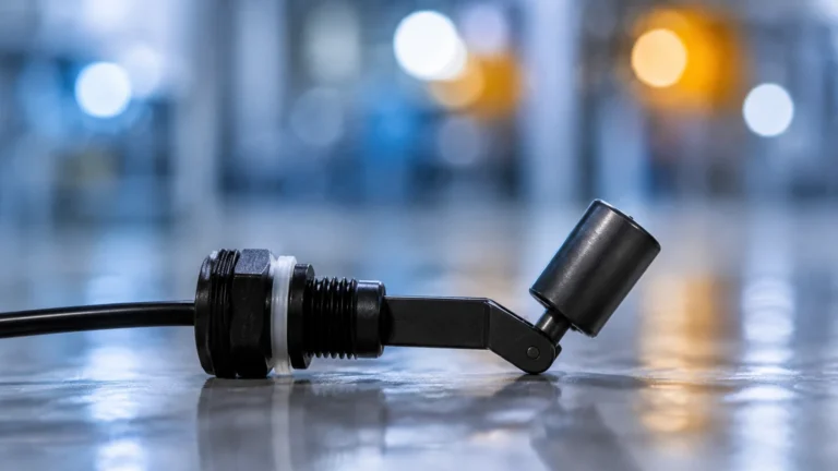
| Level Switches | Overfill protection, pump control | Point measurement only | N/A |
Installation Best Practices for Distribution Systems
Proper installation is paramount to ensuring the longevity and accuracy of instruments within a distributor line. Even the most advanced radar meter will fail to perform if mounted incorrectly.
Nozzle and Positioning
For non-contact sensors (Radar and Ultrasonic), the instrument should be mounted away from the tank wall to avoid false reflections. A general rule is to maintain a distance of at least 200 mm from the wall or 1/6th of the tank diameter. The nozzle height should be kept as short as possible to prevent the signal from "clipping" the edges of the nozzle.
Stilling Wells and Bypass Chambers
In applications with heavy foam or extreme turbulence, a stilling well (a vertical pipe inside the tank) can be used to provide a calm surface for the measurement. Similarly, magnetic level gauges utilize a bypass chamber to isolate the float from the main process turbulence.
Cable Management and Grounding
For hydrostatic transmitters and electronic sensors, proper grounding is essential to prevent signal interference from nearby heavy machinery. In outdoor installations, lightning protection and moisture-proof conduits (IP67/IP68) are mandatory to prevent water ingress into the housing.

Limitations and Environmental Constraints
No single instrument in a distributor line is a universal solution. Understanding limitations prevents costly downtime.
* Dielectric Constant ($ε_r$): Radar signals rely on the dielectric constant of the medium. Materials with very low $ε_r$ (like certain oils or dry powders) reflect less energy, requiring high-sensitivity antennas or guided-wave radar (GWR).
* Foam and Vapor: Heavy foam can absorb ultrasonic signals and scatter radar waves. While 80GHz radar is better at penetrating some vapors, dense steam can still attenuate the signal.
* Build-up and Scaling: In chemical distribution lines, crystallization or coating on the sensor face can lead to "signal loss" or inaccurate readings. Non-contact sensors are generally preferred here, but they still require periodic inspection.
The Role of OEM/ODM Services in Distributor Partnerships
A professional distributor line is often supported by OEM (Original Equipment Manufacturer) and ODM (Original Design Manufacturer) services. This allows B2B partners to customize instruments for specific market needs.
Customization options typically include:
* Material Selection: Offering PTFE, PP, or 316L Stainless Steel for wetted parts to ensure chemical compatibility.
* Communication Protocols: Integrating specific industrial IoT (IIoT) modules or wireless protocols.
* Branding: White-labeling products for regional distributors to maintain brand consistency.
By leveraging these services, distributors can provide tailored solutions that a standard "off-the-shelf" product line cannot match. For detailed technical support and to review the full range of customizable options, visiting the Main Page provides a direct path to engineering consultations.
Frequently Asked Questions (FAQ)
Q1: What is the lead time for standard items in the distributor line?
Lead times vary based on customization, but standard radar and ultrasonic sensors are typically available for shipment within 1 to 2 weeks. High-volume OEM orders may require 4 to 6 weeks depending on component availability.
Q2: Can radar level meters work in a vacuum?
Yes. Radar (electromagnetic) waves do not require a physical medium to travel, making them the ideal choice for vacuum distillation columns where ultrasonic sensors would fail.
Q3: How do I handle density changes in hydrostatic measurement?
If the density of the liquid changes (e.g., due to temperature or mixing), the hydrostatic pressure will change even if the level remains the same. In these cases, a multi-parameter system or a non-contact radar meter is recommended to avoid errors.
Q4: Are these instruments certified for hazardous areas?
Most professional distributor lines include models with ATEX, IECEx, or Ex-proof certifications for use in explosive atmospheres common in oil, gas, and chemical processing.
Q5: What maintenance is required for non-contact sensors?
Non-contact sensors require minimal maintenance. The primary task is to ensure the antenna or transducer face remains clean of significant build-up. Many modern radar units include "self-diagnostic" features that alert operators if the signal strength drops due to coating.
Conclusion
Selecting the right distributor line for level measurement is a critical decision for industrial operations. By understanding the measurement principles—from the high-frequency precision of 80GHz radar to the reliable simplicity of hydrostatic pressure—engineers can build systems that are both accurate and cost-effective. As technology evolves, the integration of smart diagnostics and robust materials continues to expand the capabilities of these essential instruments. For those looking to explore specific product configurations or seeking technical data sheets, the Main Page serves as a primary resource for industrial level measurement solutions.