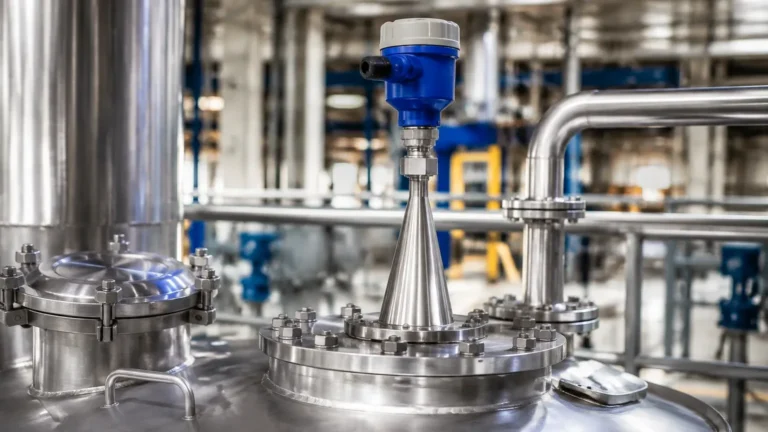
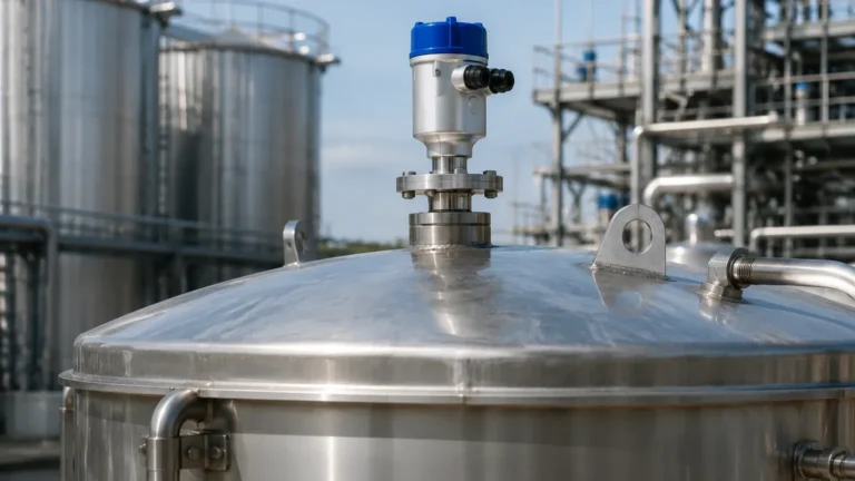
80g Radar Level Transmitter
80g Radar Level Transmitter: A Technical Engineering Guide to High-Frequency Level Measurement
In the field of industrial process automation, the demand for precision and reliability in level measurement has driven significant technological evolution. Among the various technologies available, Radar Level Meters have emerged as the gold standard for non-contact measurement. The introduction of the 80g radar level transmitter (operating at the 80 GHz frequency band) represents a major leap forward from traditional 6 GHz and 26 GHz systems. This guide explores the engineering principles, selection criteria, and practical installation considerations for 80 GHz radar technology in modern industrial environments.
1. Measurement Principles: FMCW and the 80 GHz Advantage
To understand why the 80g radar level transmitter has become a preferred choice for complex applications, one must first understand the underlying measurement principle. Most modern 80 GHz instruments utilize Frequency Modulated Continuous Wave (FMCW) technology rather than the older pulsed radar method.
The FMCW Principle
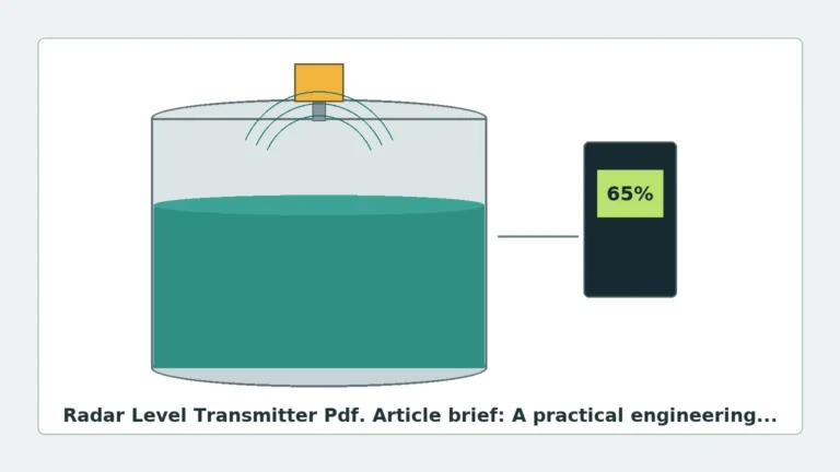
In an FMCW system, the transmitter emits a continuous signal with a frequency that varies linearly over time (a sweep). The signal travels to the surface of the medium, reflects, and returns to the antenna. Because the frequency of the emitted signal has changed during the time it took for the reflection to return, there is a frequency difference between the transmitted and received signals. This difference—known as the beat frequency—is directly proportional to the distance.
The Significance of 80 GHz
The "80g" refers to the W-band frequency (approximately 76 GHz to 81 GHz). The primary advantage of this high frequency is the bandwidth. In radar physics, the range resolution (the ability to distinguish between two close objects) is inversely proportional to the bandwidth. An 80 GHz transmitter can utilize a bandwidth of up to 4 GHz, whereas a 26 GHz transmitter is typically limited to 1 GHz or less. This allows the 80 GHz unit to achieve millimeter-level accuracy and a much smaller "blind zone" (the area near the antenna where measurement is impossible).
2. Technical Comparison: 26 GHz vs. 80 GHz
When selecting Radar Level Meters, engineers must weigh the benefits of high-frequency signals against the specific requirements of the process. The following table highlights the technical differences between the two most common industrial radar frequencies.
| Feature | 26 GHz Radar Transmitter | 80 GHz Radar Transmitter |
| :— | :— | :— |
| Beam Angle | Typically 8° to 20° | Typically 3° to 6° |
| Accuracy | ±3 mm to ±5 mm | ±1 mm to ±2 mm |
| Antenna Size | Larger (requires larger nozzles) | Compact (fits small nozzles) |
| Signal Sensitivity | Moderate | Very High (better for low DC media) |
| Dust/Vapor Resistance | Good | Excellent (due to signal processing) |
| Blind Zone | 200 mm – 400 mm | 50 mm – 100 mm |
| Process Connection | Usually ≥ DN50 (2") | Can be as small as G1" or DN25 |
3. Key Advantages of the 80g Radar Level Transmitter
Narrow Beam Angle
The most significant practical benefit of the 80 GHz frequency is the narrow beam angle. A standard 26 GHz radar with a 75 mm (3-inch) antenna has a beam angle of approximately 10 degrees. In contrast, an 80 GHz radar of the same size can achieve a beam angle as narrow as 3 degrees.
This narrow focus allows the signal to bypass internal tank obstructions such as agitators, heating coils, ladders, and baffles. It also prevents "false echoes" caused by the tank walls, which is a common issue in tall, narrow silos or small process vessels.
High Resolution and Precision
Because of the wider bandwidth, the 80g radar level transmitter provides a much higher signal-to-noise ratio. It can accurately detect the surface of media with low dielectric constants (low DC), such as plastic pellets, oils, or liquefied gases, which often produce weak reflections that lower-frequency radars might miss.
Compact Form Factor
High-frequency waves have shorter wavelengths, allowing for smaller antenna designs. This enables the installation of high-precision radar into small process connections (e.g., 1-inch threaded openings), making it ideal for pharmaceutical and food-grade applications where space is at a premium.
4. Selection Criteria for Industrial Applications
Choosing the right instrument requires a thorough analysis of the process environment. Engineers should consider the following factors:
Medium Properties
* Dielectric Constant (εr): The reflectiveness of the material. Materials with εr < 1.4 require high-sensitivity 80 GHz units.
* Physical State: Is it a liquid, slurry, or solid? For solids, the 80 GHz radar is superior at handling the irregular angles of repose found in grain or cement silos.
Process Conditions
* Temperature and Pressure: Standard units handle up to 150°C, but specialized high-temperature versions can reach 250°C or higher with cooling fins.
* Vapor and Condensation: While 80 GHz signals can be attenuated by extremely thick steam, modern signal processing algorithms (Echo Discovery) allow the 80g radar level transmitter to filter out the noise caused by condensation on the antenna lens.
Measurement Range
While 80 GHz radars are excellent for short-range precision in small tanks, they are also capable of long-range measurement in large silos, with some models reaching up to 120 meters (approx. 393 feet).
5. Installation Considerations and Constraints
Proper installation is critical to ensuring the longevity and accuracy of the device. Even with the advanced capabilities of 80 GHz technology, certain engineering rules apply:
1. Nozzle Height and Diameter: Ensure the antenna extends slightly past the bottom of the mounting nozzle to prevent signal interference from the nozzle edge. However, due to the narrow beam of the 80 GHz radar, it is much more forgiving of long nozzles than 26 GHz models.
2. Obstruction Clearance: Although the beam is narrow, the "keep-out zone" should still be checked. The radar should not be mounted directly above the filling stream to avoid signal scattering and antenna coating.
3. Orientation: For liquid applications, the transmitter should be mounted vertically (perpendicular to the liquid surface). For solids, a swivelling flange (aiming flange) is often recommended to align the beam with the material's angle of repose to maximize signal return.
4. Avoid Vacuum and High Pressure Extremes without Proper Sealing: Ensure the process seal (typically PTFE or PEEK) is compatible with the chemical aggressiveness of the medium.

6. Application Risks and Limitations
Despite its versatility, the 80g radar level transmitter is not a universal solution for every scenario:
* Heavy Foam: Extremely thick, dense foam can absorb high-frequency radar signals. In cases of persistent, thick foam, a guided wave radar (GWR) or a lower-frequency 6 GHz radar might be more reliable.
* Cost Sensitivity: 80 GHz technology generally carries a higher price point than 26 GHz or ultrasonic sensors. For simple water tank applications where ±10 mm accuracy is acceptable, an ultrasonic sensor may be more cost-effective.
* Signal Attenuation: In very high-pressure applications (above 40 bar) involving certain gases like CO2, the density of the gas can attenuate the 80 GHz signal more significantly than a lower-frequency signal.
7. Buyer’s Checklist: Confirming Specifications with Manufacturers
When sourcing an 80g radar level transmitter from an international manufacturer like Welk, buyers should confirm the following technical details to ensure the instrument is fit for purpose:
1. Explosion-Proof Ratings: Does the application require ATEX, IECEx, or local certifications for hazardous zones?
2. Output Protocol: Is the standard 4-20mA HART sufficient, or is RS485 Modbus, Profibus, or Foundation Fieldbus required for integration into the DCS?
3. Antenna Material: Is the lens made of PTFE (standard) or is a specialized material required for high-temperature or corrosive environments?
4. Calibration and Configuration: Does the manufacturer provide a Bluetooth app or PC-based software for remote configuration? This is vital for tanks that are difficult to access.
8. Frequently Asked Questions (FAQ)
Q: Can 80 GHz radar measure through a plastic tank lid?
A: Yes. Because 80 GHz signals can penetrate non-conductive materials like PE, PP, or PVC, the transmitter can often measure the level from outside the tank, provided the lid is not too thick and does not contain metal reinforcement.
Q: Does dust affect the 80 GHz signal?
A: 80 GHz radar performs exceptionally well in dusty environments (like cement or flour silos). The high frequency and advanced signal processing allow it to distinguish between the solid surface and the dust cloud.
Q: What is the minimum dielectric constant an 80 GHz radar can measure?
A: Most high-quality 80 GHz transmitters can measure media with a dielectric constant as low as 1.4. For lower values, a stilling well or a guided wave radar might be necessary.
Conclusion
The 80g radar level transmitter has redefined the boundaries of non-contact level measurement. By offering a narrower beam, higher precision, and the ability to operate in confined spaces, it solves many of the traditional challenges associated with older radar frequencies. For B2B buyers and process engineers, the transition to 80 GHz represents an investment in higher process reliability and reduced maintenance. When selecting these instruments, focusing on the specific dielectric properties of the medium and the physical constraints of the vessel will ensure the most effective implementation of this advanced technology.