Line Sensors
Line Sensors
In the landscape of industrial automation and process control, line sensors represent a critical category of detection technology used to monitor position, edge alignment, and continuous levels. While the term is frequently associated with optical array sensors used in web guiding and assembly lines, its application in level measurement is equally vital. In the context of fluid and solid storage, line sensors—often referred to as continuous level probes or linear position transmitters—provide a constant stream of data regarding the height of a substance within a vessel.
Understanding the operational principles, selection criteria, and installation requirements of these sensors is essential for engineers tasked with optimizing process efficiency and ensuring safety. This guide examines the technical foundations of line sensing technologies and their practical implementation in industrial environments.
Measurement Principles of Line Sensors
Line sensors operate by detecting changes along a linear axis. Depending on the physical property being measured, the technology utilized can vary significantly. In industrial level measurement, the most common principles include magnetostriction, electromagnetic wave reflection, and optical pixel arrays.
1. Magnetostrictive Linear Sensing
Magnetostrictive line sensors are widely used for high-precision level measurement. The principle relies on the interaction between two magnetic fields. A low-current interrogation pulse is sent down a waveguide made of magnetostrictive material. When this pulse meets the magnetic field of a float (which moves along the "line" of the probe), a torsional strain wave is generated. This wave travels back to the sensor head at a known speed. By measuring the time-of-flight between the initial pulse and the return wave, the sensor determines the exact position of the float with sub-millimeter accuracy.
2. Guided Wave Radar (GWR)
Guided Wave Radar acts as a line sensor by directing high-frequency microwave pulses along a physical probe (a cable or rod). When the pulse encounters a medium with a different dielectric constant (such as the surface of a liquid), a portion of the energy is reflected back to the transmitter. Because the pulse is guided along a line, it is less susceptible to interference from tank obstructions or foam compared to through-air radar. This technology is particularly effective for measuring interfaces between two different liquids.
3. Optical Line Arrays
In factory automation, optical line sensors utilize a linear array of CCD (Charge-Coupled Device) or CMOS pixels. A light source (laser or LED) projects a line across the target. The sensor detects the reflection or the shadow cast by the object. By analyzing which pixels are illuminated, the processor determines the position, width, or edge of the material. This is common in paper mills, textile production, and packaging lines where material alignment is critical.
4. Capacitive Linear Probes
Capacitive sensors function as line sensors by measuring the change in capacitance between a central probe and the surrounding tank wall (or a reference ground). As the level of the medium rises along the length of the probe, the dielectric constant in the gap changes, leading to a proportional change in capacitance. This is converted into a linear 4-20mA or digital signal representing the level.
Selection Criteria for Industrial Applications
Selecting the appropriate line sensor requires an evaluation of the physical environment, the characteristics of the medium, and the required precision. Engineers should consult the Main Page of technical manufacturers to review specific performance curves and material compatibility charts before finalizing a selection.
Media Characteristics
* Dielectric Constant (DK): For radar and capacitive sensors, the DK of the material is the primary factor in signal strength. Low DK materials (like oils) require high-sensitivity probes or guided wave configurations.
* Viscosity and Coating: Highly viscous liquids can coat the probe of a line sensor, leading to false readings. In such cases, non-contact ultrasonic or through-air radar may be preferred over contact-based line sensors.
* Corrosivity: The probe material must be chemically compatible with the medium. Common materials include 316L stainless steel, PTFE, and Hastelloy.
Environmental Conditions
* Pressure and Temperature: High-pressure vessels (exceeding 40 bar) or extreme temperatures (above 200°C) require specialized sensor housings and seals, such as ceramic-to-metal hermetic seals.
* Turbulence: In tanks with agitators, a rigid rod line sensor may require additional bracing or a stilling well to prevent mechanical fatigue.
Performance Requirements
| Feature | Magnetostrictive | Guided Wave Radar | Optical Array | Capacitive |
| :— | :— | :— | :— | :— |
| Accuracy | ±0.5 mm to ±1 mm | ±2 mm to ±5 mm | ±0.01 mm | ±1% of span |
| Max Range | 6 meters | 30+ meters | 0.5 meters | 3 meters |
| Contact | Yes (Float) | Yes (Probe) | No | Yes |
| Best Use | Custody transfer | Process tanks | Edge detection | Simple liquids |
Installation Considerations and Best Practices
Correct installation is paramount to the reliability of line sensors. Even the most advanced sensor will fail to provide accurate data if mechanical and electrical installation guidelines are ignored.
Mounting Orientation
Line sensors used for level measurement must be mounted vertically. Any deviation from the vertical axis can introduce cosine errors in the measurement and may cause mechanical binding in float-based systems like magnetostrictive sensors. For optical line sensors used in web guiding, the sensor must be perpendicular to the material path to avoid parallax errors.
The "Dead Zone" or Null Zone
Every linear sensor has a "dead zone" at the top and bottom of its range where measurement is impossible or inaccurate.
1. Upper Dead Zone: The distance from the process connection to the highest point of reliable measurement. This is often where the electronics are housed.
2. Lower Dead Zone: The area at the tip of the probe where the signal cannot be accurately processed.
Engineers must ensure that the tank's operational range falls within the sensor's active measurement span.
Signal Interference and Shielding
Industrial environments are rife with electromagnetic interference (EMI). Line sensors should be connected using shielded, twisted-pair cabling. The shield should be grounded at one end (typically the control room side) to prevent ground loops. For radar-based line sensors, the probe should be kept away from internal tank structures like ladders, pipes, and agitators to prevent parasitic reflections.
Common Risks and Limitations
While line sensors are robust, they are not universal solutions. Understanding their limitations prevents costly downtime.
* Mechanical Stress: Long probe-style line sensors (especially those exceeding 3 meters) are susceptible to bending moments caused by heavy fluid flow or solids loading. In these applications, flexible cable probes with end weights are often used instead of rigid rods.
* Build-up and Scaling: In wastewater or mining slurries, material can build up on the probe. While some guided wave radar systems use advanced algorithms to "see through" coating, excessive buildup will eventually attenuate the signal or cause a "bridging" effect where the sensor reads a constant high level.
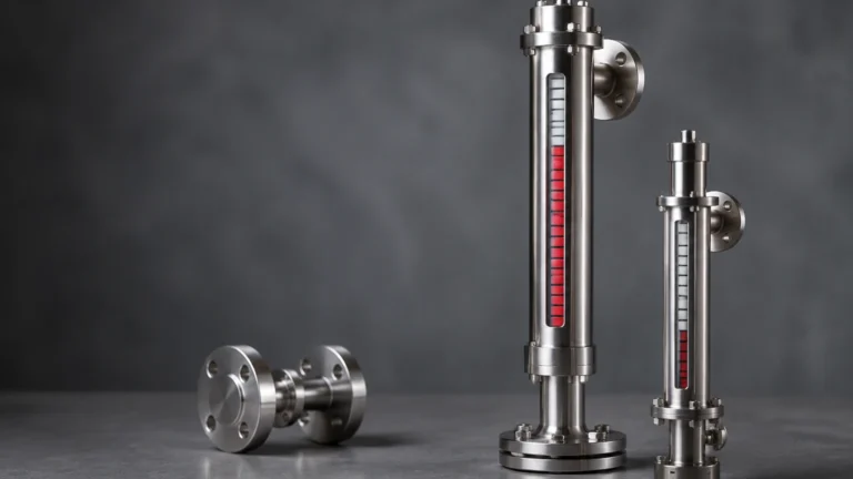
* Vapor and Steam: High-density steam can slow down the travel time of radar pulses, leading to a measurement error. For high-pressure boiler applications, compensation factors or specialized magnetic level gauges with magnetostrictive transmitters are often employed.
Practical Selection Table for Level Applications
| Application | Recommended Line Sensor | Reason |
| :— | :— | :— |
| Fuel Storage | Magnetostrictive | High accuracy required for inventory and leak detection. |
| Chemical Reactor | Guided Wave Radar | Handles varying temperatures and pressures without recalibration. |
| Conveyor Alignment | Optical Line Array | High-speed non-contact detection of material edges. |
| Acid Tanks | PTFE-coated Capacitive | Excellent chemical resistance and simple electronics. |
| High-Pressure Steam | Magnetic Level Gauge | Provides visual safety backup plus continuous electronic output. |
Frequently Asked Questions (FAQ)
Q: Can line sensors be used for solids measurement?
A: Yes, Guided Wave Radar (GWR) is an excellent line sensor for solids like powders and grains. However, the probe must be rated for the high tensile loads that occur when solids are discharged from the silo.
Q: What is the difference between a line sensor and a point level switch?
A: A point level switch only detects if a material has reached a specific height (on/off). A line sensor provides continuous measurement across a range (e.g., 0% to 100% full).
Q: How often do line sensors require calibration?
A: Most modern digital line sensors, especially radar and magnetostrictive types, are factory-calibrated and do not drift over time. However, annual verification is recommended for safety-critical or custody-transfer applications.
Q: Can I cut a line sensor probe to length in the field?
A: Some guided wave radar and capacitive probes are field-cuttable, but magnetostrictive probes are typically not. Always check the manufacturer's documentation before attempting to modify a probe.
Conclusion
Line sensors are indispensable tools for achieving precision in industrial process control. Whether utilizing the high-speed pixel analysis of optical arrays or the robust time-of-flight measurements of guided wave radar, these instruments provide the data necessary for automated decision-making. By carefully considering the media properties, environmental constraints, and installation requirements, engineering teams can implement sensing solutions that enhance both productivity and safety. For further technical specifications and to explore a wide range of industrial measurement instruments, professionals should refer to the Main Page for detailed product support and engineering resources.