Lift Stations for Sewer
Lift Stations for Sewer
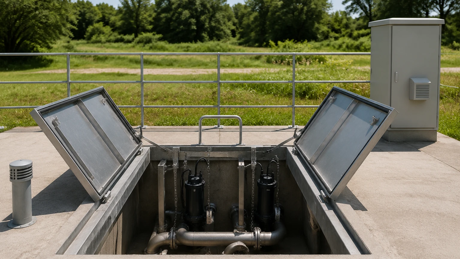
In modern municipal and industrial wastewater management, lift stations for sewer systems play a critical role in moving effluent through the collection network. When the topography of a region does not allow for continuous gravity-fed flow, these stations—also known as pump stations—provide the necessary lift to move wastewater to higher elevations or directly to a treatment plant. Because these environments are inherently harsh, containing corrosive gases, grease, and solids, the selection of reliable level measurement instrumentation is paramount to prevent overflows and optimize pump efficiency.
Accurate level monitoring ensures that pumps are activated and deactivated at the correct intervals, preventing dry running or motor burnout while managing the inflow effectively. This article provides a comprehensive engineering reference for the technologies used to monitor and control lift stations for sewer applications.
Understanding Level Measurement Principles
Before selecting a specific instrument, it is essential to understand the physics behind the most common measurement technologies used in wastewater lift stations. Each method has distinct advantages depending on the specific characteristics of the sewer environment.
1. Ultrasonic Level Measurement
Ultrasonic sensors operate on the "time-of-flight" principle. The sensor emits an ultrasonic pulse that travels through the air, reflects off the liquid surface, and returns to the transducer. By measuring the time taken for the pulse to return and knowing the speed of sound, the device calculates the distance to the liquid level.
* Advantages: Non-contact measurement, relatively low cost, and easy to install.
* Limitations: The speed of sound is affected by temperature fluctuations and gas concentrations (like methane or H2S). Furthermore, heavy foam or steam can absorb the signal, leading to inaccurate readings.
2. Radar Level Measurement (FMCW)
Radar level meters, particularly those operating at high frequencies like 80GHz, use Frequency Modulated Continuous Wave (FMCW) technology. The sensor transmits a continuous signal with a changing frequency. The difference between the transmitted and received frequency is proportional to the distance.
* Advantages: Non-contact and unaffected by temperature, pressure, or gas composition. Radar can penetrate light foam and is highly accurate even in turbulent conditions.
* Limitations: Higher initial capital expenditure compared to ultrasonic or hydrostatic sensors.
3. Hydrostatic Pressure Measurement
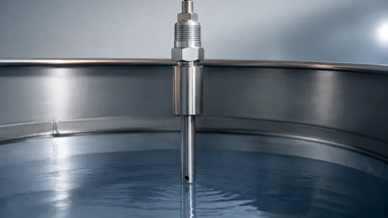
This method uses a submersible pressure transmitter placed at the bottom of the wet well. The sensor measures the head pressure exerted by the liquid column above it. Since the density of wastewater is relatively constant (close to 1.0 g/cm³), the pressure reading is directly proportional to the level.
* Advantages: Not affected by surface foam, turbulence, or surface objects.
* Limitations: The sensor is in direct contact with the wastewater. It is susceptible to fouling from grease, rags, and sludge, requiring regular cleaning to ensure the sensing diaphragm remains unobstructed.
4. Float Switches and Conductivity Probes
These are point-level detection devices. Float switches move with the liquid level to mechanically trigger a switch, while conductivity probes detect the presence of liquid via electrical resistance.
* Advantages: Extremely simple and robust.
* Limitations: They do not provide continuous level data and are prone to "ragging" (becoming entangled in debris).
Technology Selection for Sewer Lift Stations
Choosing the right technology for lift stations for sewer requires a balance between budget, maintenance capabilities, and the specific physical characteristics of the wet well. The following table compares the primary continuous measurement technologies:
| Feature | Ultrasonic | Radar (80GHz) | Hydrostatic |
| :— | :— | :— | :— |
| Measurement Type | Non-contact | Non-contact | Contact (Submerged) |
| Accuracy | ±0.25% to 0.5% | ±1 mm to 2 mm | ±0.1% to 0.5% |
| Foam Resistance | Poor to Moderate | Good | Excellent |
| Grease/Fouling Resistance | Excellent | Excellent | Poor |
| Gas/Vapor Impact | High | Negligible | None |
| Installation Ease | High | High | Moderate |
| Typical Lifespan | 5–8 years | 10+ years | 3–5 years (in harsh sewage) |
For engineers looking to standardize their fleet, many professional manufacturers like Welk offer a range of these instruments tailored for industrial automation. You can Review product options and application support on the Welk Main Page to determine which specific model fits your infrastructure requirements.
Installation Considerations and Best Practices
Proper installation is just as important as selecting the right sensor. In the confined and turbulent environment of a sewer lift station, several factors must be addressed during the design phase.
Avoiding the Inflow Stream
Sensors should never be installed directly above or near the inflow pipe. The falling water creates turbulence, air bubbles, and foam, all of which can interfere with ultrasonic and radar signals. For hydrostatic sensors, the physical force of the inflow can cause the sensor to swing or sustain mechanical damage.
Managing the "Dead Zone"
All non-contact sensors have a "dead zone" or "blind zone" (typically 100 mm to 500 mm) directly beneath the transducer where measurement is impossible. Ensure the sensor is mounted high enough so that the maximum expected liquid level never enters this zone.
Mounting and Positioning
* Vertical Alignment: Non-contact sensors must be mounted perfectly perpendicular to the liquid surface to ensure the signal reflects back to the receiver.
* Wall Interference: Sensors should be mounted away from the wet well walls (typically at least 200 mm to 300 mm) to avoid false echoes from wall buildup or structural ribs.
* Stilling Wells: In extremely turbulent stations, a stilling well (a vertical pipe with vent holes) can be used to provide a calm surface for the sensor to measure. However, these are prone to clogging with grease in sewer applications.
Chemical Compatibility
Sewer environments are high in Hydrogen Sulfide (H2S), which is highly corrosive. Sensors should be constructed from resistant materials such as PVDF, PP, or high-grade stainless steel (316L). For hydrostatic sensors, the cable jacket should be made of PUR (polyurethane) or FEP to prevent chemical degradation over time.
Common Risks and Mitigation Strategies
Operating lift stations for sewer involves managing several environmental risks that can lead to instrument failure or false readings.
1. Grease and "Fatbergs"
Grease is a major challenge in municipal sewage. It tends to float on the surface and coat everything it touches.
* Risk: Hydrostatic sensors become "blinded" by grease coatings. Ultrasonic sensors may receive weak signals if a thick grease crust forms.
* Mitigation: Use non-contact radar for the primary level signal. If using hydrostatic sensors, choose models with a flush diaphragm and schedule monthly cleanings.
2. Foam and Surface Agitation
Foam is common in stations receiving industrial runoff or high-velocity inflow.
* Risk: Foam absorbs ultrasonic pulses, causing the sensor to report a "lost echo" or an incorrect high level.
* Mitigation: 80GHz radar is generally more effective at penetrating foam. If foam is persistent, a hydrostatic sensor is the most reliable option as it measures from the bottom up.
3. Condensation and Steam
In warmer climates or industrial zones, the temperature difference between the sewage and the ambient air can cause heavy condensation on the sensor face.
* Risk: Water droplets on an ultrasonic transducer can attenuate the signal.
* Mitigation: Modern radar sensors often feature a convex lens design that allows condensation to drip off, preventing signal blockage.
Redundancy and Safety Integration
In critical lift stations for sewer, relying on a single instrument is a significant risk. Best practices dictate a redundant system:
1. Primary Level: A non-contact Radar or Ultrasonic transmitter providing a 4-20mA or RS485 Modbus signal to the PLC/SCADA system.
2. Secondary/Backup Level: A hydrostatic pressure transmitter to verify the primary reading.
3. High/Low Alarms: Independent float switches set at the absolute maximum and minimum levels. These should be wired directly to the pump motor starters or a separate alarm circuit to provide a "fail-safe" stop/start regardless of the PLC status.
Frequently Asked Questions (FAQs)
Q: How often should I calibrate the level sensors in a sewer lift station?
A: For non-contact sensors, an annual check is usually sufficient unless there is significant buildup. Hydrostatic sensors should be checked every 3 to 6 months to ensure the diaphragm is clean and the zero-point hasn't drifted due to sediment.
Q: Can I use a radar sensor in a very narrow wet well?
A: Yes, especially 80GHz radar. These have a very narrow beam angle (often as low as 3 degrees), which allows them to measure in tight spaces without hitting the walls or internal piping.
Q: What is the best way to protect sensors from lightning strikes?
A: Lift stations are often in isolated areas and are prone to surges. Ensure all instruments are grounded correctly and install surge protection devices (SPDs) on the signal loops at both the sensor end and the control panel end.
Q: How do I handle H2S gas buildup near the electronics?
A: Use sensors with fully potted electronics and IP68 ratings. Ensure that the conduit entries are sealed with gas-tight fittings to prevent corrosive gases from traveling up the conduit into the main control panel.
Conclusion
Effective management of lift stations for sewer requires a deep understanding of both the hydraulic requirements of the system and the limitations of level measurement technology. By prioritizing non-contact methods like radar for their low maintenance and high accuracy, and supplementing them with robust point-level backups, operators can ensure long-term reliability and environmental safety. For those seeking advanced measurement solutions, visiting the Main Page of a specialized manufacturer like Welk provides access to the technical specifications and engineering support necessary to optimize wastewater infrastructure.