Hydraulic Level Switch
Hydraulic Level Switch
In industrial fluid power systems, maintaining the correct fluid volume is critical for operational safety and component longevity. A hydraulic level switch serves as a fundamental protective device, designed to monitor the oil level within a reservoir or tank and provide a discrete electrical signal when the level reaches a predetermined high or low point. This data is essential for preventing pump cavitation, ensuring adequate cooling, and protecting the system from catastrophic failure due to leaks or overfilling.
Selecting the appropriate hydraulic level switch requires an understanding of the specific physical properties of hydraulic fluids, the dynamics of the reservoir environment, and the electrical requirements of the control system. This guide provides a technical overview of measurement principles, selection criteria, and installation best practices for engineers and maintenance professionals.
Measurement Principles of Hydraulic Level Switches
Hydraulic level switches operate using various physical principles to detect the presence or absence of fluid. In the context of hydraulic systems, where fluids are typically non-conductive mineral oils or synthetic esters, the following technologies are most prevalent.
Magnetic Float Technology
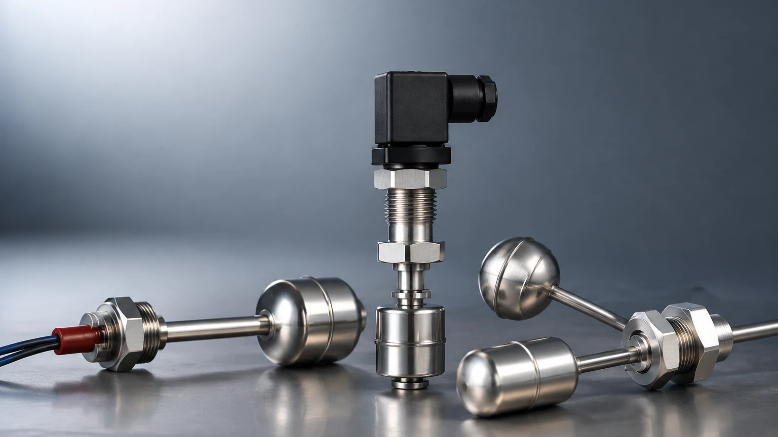
This is the most common technology used in hydraulic applications. A magnetic float switch consists of a hollow float containing a permanent magnet that moves along a stationary stem. Inside the stem, one or more hermetically sealed reed switches are positioned at specific set points. As the fluid level rises or falls, the float moves the magnet into proximity with the reed switch, causing the contacts to open or close.
* Advantages: Simple, reliable, and requires no external power to operate the sensing element. It is highly compatible with a wide range of oil densities.
* Limitations: Susceptible to mechanical jamming if the oil contains significant metallic debris or high levels of sludge.
Optical Sensing
Optical level switches utilize an infrared LED and a light receiver housed within a prism. When the sensor tip is in the air, the infrared light is reflected internally within the prism back to the receiver. When the tip is submerged in hydraulic oil, the light is refracted into the fluid, causing the receiver to detect a change in light intensity.
* Advantages: No moving parts, compact size, and high resistance to pressure and temperature.
* Limitations: Performance can be degraded by highly aerated oil (foam) or heavy coating on the sensor tip.
Capacitive Sensing
Capacitive switches measure the change in electrical capacitance between the sensor probe and the tank wall (or a reference electrode) as the fluid level changes. Since hydraulic oils have a different dielectric constant than air, the sensor can accurately detect the presence of the fluid.
* Advantages: Solid-state design with no moving parts; capable of detecting levels through non-metallic tank walls.
* Limitations: Requires calibration to the specific dielectric constant of the hydraulic fluid used and can be sensitive to moisture contamination in the oil.
Selection Criteria for Hydraulic Applications
When specifying a hydraulic level switch, engineers must evaluate the operating environment against the instrument's technical limits. For comprehensive specifications and component options, engineers may refer to the Main Page of industrial instrumentation providers to compare specific model tolerances.
Fluid Compatibility and Viscosity
Hydraulic systems use a variety of fluids, from standard mineral oils (ISO VG 32, 46, 68) to fire-resistant fluids like water-glycol or synthetic esters. The switch materials—typically stainless steel, brass, or high-grade polymers—must be chemically compatible with these fluids. Furthermore, the viscosity of the oil at cold start-up temperatures (which can exceed 1000 cSt) must not impede the movement of mechanical floats.
Temperature and Pressure
Reservoir temperatures in industrial hydraulics typically range from 40°C to 80°C, but localized temperatures or specific applications may reach 100°C or higher. The switch must be rated for the maximum possible temperature to prevent seal failure or electrical drift. While most reservoir switches are atmospheric, those mounted in pressurized return lines or sealed tanks must be rated for the system's internal pressure.
Selection Comparison Table
| Feature | Magnetic Float | Optical | Capacitive |
| :— | :— | :— | :— |
| Moving Parts | Yes | No | No |
| Media Viscosity | Low to Medium | Low to High | Low to Medium |
| Pressure Rating | Up to 40 bar | Up to 100+ bar | Up to 20 bar |
| Temperature Range | -20°C to +120°C | -30°C to +125°C | -40°C to +100°C |
| Foam Sensitivity | Low | High | Moderate |
| Coating Sensitivity | Moderate | High | High |
Installation and Mounting Considerations
Proper installation is critical to ensure the hydraulic level switch provides accurate signals and survives the harsh vibration common in hydraulic power units (HPUs).
1. Mounting Orientation: Switches are typically available in top-mount (vertical) or side-mount (horizontal) configurations. Vertical switches allow for multiple set points (e.g., low-level warning and low-low-level shutdown) on a single stem. Horizontal switches are often used for simple high or low alerts where vertical space is limited.
2. Baffles and Turbulence: In reservoirs with high return flow rates, the fluid surface can be turbulent. Installing the switch behind a baffle or using a stilling well (a protective tube around the float) prevents "chattering" of the switch contacts caused by surface waves.
3. Electrical Integration: Most hydraulic level switches offer Normally Open (NO) or Normally Closed (NC) configurations. For safety-critical low-level detection, a "closed circuit" (NC) in the safe state is preferred, as this ensures that a broken wire or loss of power will trigger a fail-safe alarm.
4. Connector Standards: In modern industrial automation, M12 or DIN 43650 connectors are standard for hydraulic sensors, providing IP65 or IP67 protection against oil mist and moisture.
Common Risks and Maintenance
Despite their simplicity, hydraulic level switches can fail if not properly maintained or if the system conditions change.
* Ferrous Contamination: In systems with significant component wear, fine metallic particles can accumulate on the magnetic float of a reed-type switch. This increases the weight of the float and can eventually cause it to sink or stick. Regular oil analysis and magnetic filtration are recommended.
* Sludge Accumulation: Over time, hydraulic oil can degrade, forming a varnish or sludge. This buildup can coat optical prisms or capacitive probes, leading to false readings. Periodic cleaning of the sensing element during oil changes is a best practice.
* Electrical Surges: Switching inductive loads (like large relay coils) directly through a small reed switch can cause the contacts to weld together. Always use an interface relay or ensure the switch is protected by a suppression circuit (snubber).
Frequently Asked Questions (FAQs)
Q: Can I use a level switch designed for water in a hydraulic oil tank?
A: Generally, no. Hydraulic oil is less dense than water (typically 0.85 to 0.90 g/cm³ compared to 1.0 g/cm³). A float designed for water may not have sufficient buoyancy to rise in oil, leading to a permanent "low level" signal.
Q: How do I handle foaming in the hydraulic reservoir?
A: Foaming is often a sign of air ingestion or fluid degradation. From a sensing perspective, magnetic float switches are the least affected by foam. Optical sensors may struggle as the foam can scatter the light beam, leading to erratic signals.
Q: What is the difference between a level switch and a level transmitter?
A: A level switch provides a discrete "on/off" signal at a specific point. A level transmitter provides a continuous signal (such as 4-20mA or 0-10V) representing the exact fluid level across a range. Switches are typically used for emergency protection, while transmitters are used for process control and inventory management.
Q: What thread sizes are standard for hydraulic level switches?
A: Most industrial units use BSP (G) threads or NPT threads. Common sizes include G1/2", G1", and 1/2" NPT. Some mobile hydraulic applications may use SAE straight threads with O-ring seals.
For engineers seeking to integrate these components into a larger automation framework, reviewing the technical documentation on the Main Page of specialized manufacturers can provide the necessary wiring diagrams and chemical compatibility charts required for a robust design. Ensuring the switch is correctly matched to the fluid type and environmental conditions is the most effective way to prevent unplanned downtime in hydraulic systems.