Sensor Water Level
Sensor Water Level
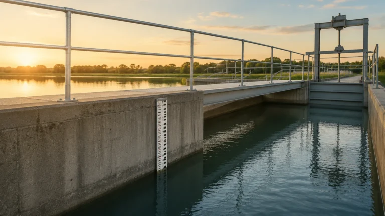
In industrial process control, the term "sensor water level" refers to a broad category of instrumentation designed to monitor and manage the height of water or water-based liquids within tanks, reservoirs, open channels, and sumps. Accurate level measurement is critical for operational efficiency, safety, and inventory management across sectors such as water treatment, chemical processing, and industrial automation. As a professional manufacturer, Welk provides a comprehensive suite of technologies—ranging from non-contact radar to submersible hydrostatic transmitters—to address the diverse challenges of water level monitoring.
Selecting the appropriate sensor water level technology requires an understanding of the underlying physics of each measurement method, the environmental conditions of the application, and the specific requirements for accuracy and maintenance. This guide serves as a practical engineering reference for evaluating and implementing water level sensing solutions.
Principles of Water Level Measurement
Before selecting a device from the Main Page, engineers must understand the operating principles of the primary sensing technologies used in modern industry.
Ultrasonic Level Sensors
Ultrasonic sensors operate on the "time-of-flight" principle. The sensor emits high-frequency sound waves from a transducer located at the top of the vessel. These waves travel through the air, reflect off the water surface, and return to the sensor. By measuring the time interval between emission and reception, the device calculates the distance to the water surface. Since the height of the tank is known, the sensor determines the current water level.
* Advantages: Non-contact, cost-effective, and easy to install.
* Limitations: Performance can be affected by heavy foam, extreme turbulence, or significant temperature fluctuations that alter the speed of sound.
Radar Level Meters (FMCW and Pulse)
Radar sensors use electromagnetic waves (typically in the 26GHz or 80GHz range) rather than sound waves. Frequency Modulated Continuous Wave (FMCW) radar is the current industry standard for high-precision applications. The sensor emits a continuous signal with a varying frequency; the difference between the emitted and received frequency is proportional to the distance.
* Advantages: Unaffected by vacuum, high pressure, dust, or temperature changes. 80GHz radar offers a narrow beam angle, allowing for measurement in narrow tanks or vessels with internal obstructions.
* Limitations: Higher initial capital expenditure compared to ultrasonic or hydrostatic options.
Hydrostatic Level Transmitters
Hydrostatic sensors measure the liquid level based on the physical relationship between the height of a liquid column and the pressure it exerts at the base. The formula $P = \rho \cdot g \cdot h$ (where $P$ is pressure, $\rho$ is density, $g$ is gravity, and $h$ is height) allows the sensor to convert pressure readings into precise level data. These are often submersible probes or flange-mounted pressure transmitters.
* Advantages: Highly reliable for deep wells, reservoirs, and vented tanks. They are immune to surface conditions like foam or vapor.
* Limitations: Accuracy depends on constant liquid density. In closed tanks, a differential pressure setup is required to account for headspace pressure.
Magnetic Level Gauges and Switches
Magnetic level gauges utilize a float containing a permanent magnet that moves with the water level inside a bypass chamber. This magnet actuates external visual indicators or electronic switches. While often used for visual confirmation, they can be equipped with reed-chain transmitters for continuous 4-20mA output.
Selection Criteria for Water Level Sensors
Choosing a sensor water level solution involves more than just matching a probe to a tank. Engineers must evaluate the following technical parameters to ensure long-term reliability.
1. Media Characteristics
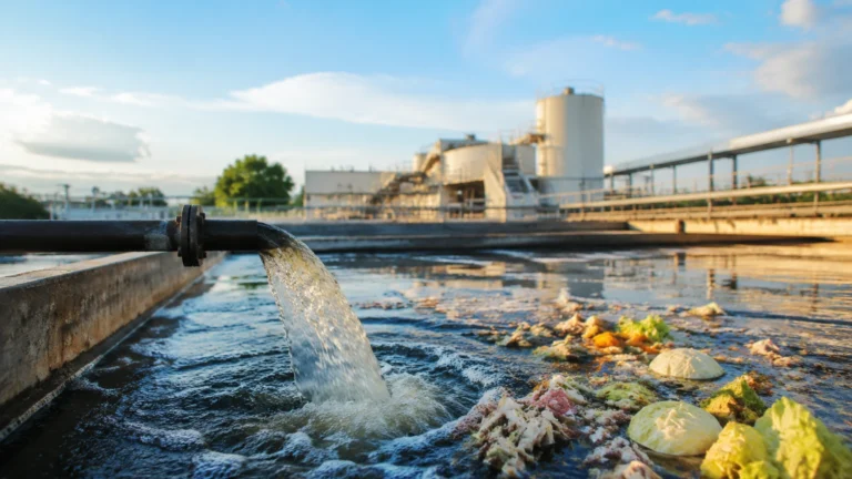
While the primary medium is water, the presence of additives, chemicals, or solids changes the requirements. For example, wastewater with high solids content may foul a submersible hydrostatic sensor, making non-contact radar a better choice. In the chemical industry, corrosive additives require sensors with PTFE or PVDF wetted parts.
2. Tank Geometry and Obstructions
Internal structures such as agitators, heating coils, or ladders can create false echoes for ultrasonic and radar sensors. In these scenarios, a high-frequency (80GHz) radar with a narrow beam angle is preferred to "steer" the signal around obstructions. Alternatively, a guided wave radar (GWR) can be used to track the level along a probe.
3. Environmental Conditions
Outdoor installations must account for seasonal temperature variations and potential lightning strikes. Sensors with integrated temperature compensation and surge protection are essential. For applications involving steam or heavy vapor, radar is superior to ultrasonic technology, as electromagnetic waves are not attenuated by air density changes.
4. Accuracy and Output Requirements
Standard industrial applications typically require accuracy within ±2mm to ±5mm. However, custody transfer or high-precision chemical dosing may require sub-millimeter accuracy. Common outputs include 4-20mA (HART), RS485 (Modbus), or wireless protocols for remote monitoring sites.
Technical Selection Table
| Technology | Typical Accuracy | Max Range | Contact Type | Best Suited For |
| :— | :— | :— | :— | :— |
| Ultrasonic | ±0.25% of range | 15 – 20m | Non-contact | Open channels, plastic tanks, water sumps |
| 80GHz Radar | ±1mm | 120m | Non-contact | Narrow tanks, turbulent surfaces, chemical tanks |
| Hydrostatic | ±0.1% to 0.5% | 200m+ | Submerged | Deep wells, water towers, vented reservoirs |
| Guided Wave Radar | ±2mm | 30m | Contact | Small vessels with steam or low dielectric liquids |
| Magnetic Gauge | ±5mm to 10mm | 6m | Contact | High-pressure boilers, visual level indication |
Installation Considerations and Best Practices
Proper installation is as critical as sensor selection. Even the most advanced sensor water level device will fail to provide accurate data if positioned incorrectly.
Positioning and Dead Zones
Every non-contact sensor has a "dead zone" or "blocking distance" near the transducer face where measurement is impossible. Ensure the sensor is mounted high enough that the maximum water level never enters this zone. For ultrasonic sensors, this is typically 0.25m to 0.8m depending on the model.
Avoiding Turbulence and Foam
If the water surface is highly turbulent due to an inlet pipe, the sensor should be installed in a stilling well or a quieter section of the tank. Foam acts as an absorber for ultrasonic waves; if foam is persistent, hydrostatic or high-frequency radar sensors are the recommended alternatives.
Mounting Alignment
For radar and ultrasonic devices, the sensor must be mounted perpendicular to the liquid surface. A deviation of even a few degrees can result in a significant loss of signal strength, especially in tall, narrow silos or tanks. Using adjustable flanges or aiming kits can help optimize the signal return.
Cable Management for Submersible Sensors
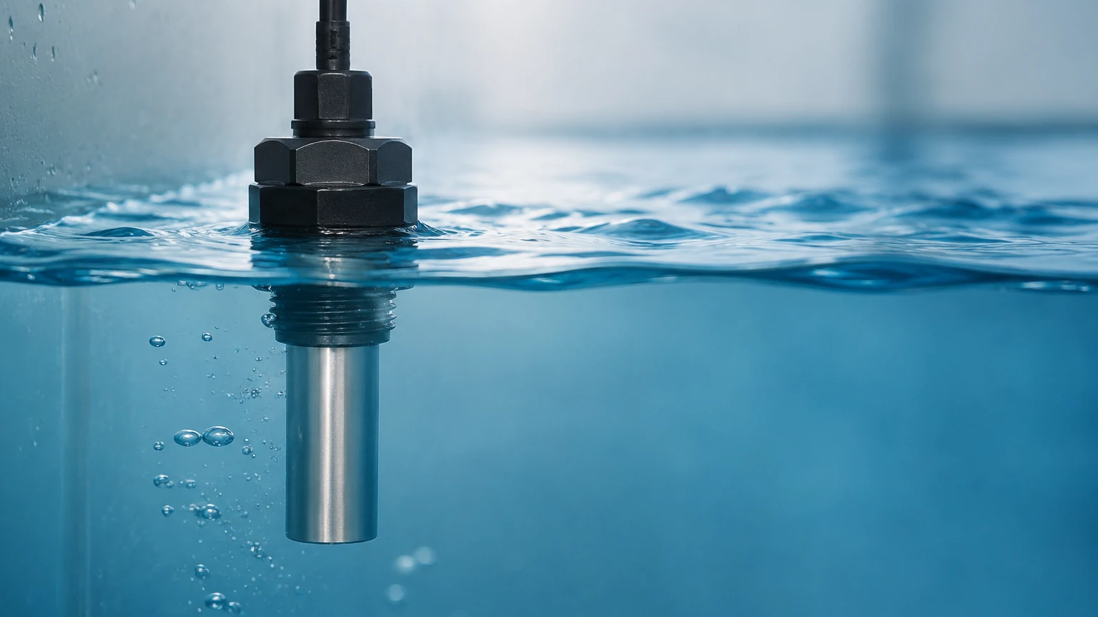
Hydrostatic submersible sensors rely on a vented cable to equalize the internal sensor pressure with atmospheric pressure. It is vital to ensure the vent tube is not kinked and is protected from moisture ingress using a desiccant filter or a specialized junction box.
Common Risks and Limitations
Engineers should be aware of the following risks when deploying water level sensors:
1. Signal Interference: In metal tanks, multiple reflections (multipath interference) can confuse ultrasonic sensors. Radar sensors with advanced software algorithms can usually filter these out.
2. Build-up and Scaling: In hard water or wastewater applications, calcium carbonate or biological growth can accumulate on the sensor face. Non-contact sensors are less susceptible, but even they may require periodic cleaning if the build-up becomes extreme.
3. Power Supply Stability: Industrial sensors are sensitive to voltage fluctuations. Using a stabilized 24V DC power supply and shielded cabling is necessary to prevent signal noise and electronic failure.
4. Pressure Limits: Submersible sensors have a maximum depth rating. Exceeding this can rupture the sensing diaphragm, leading to permanent damage.
Frequently Asked Questions (FAQs)
Q: Can I use an ultrasonic sensor for boiling water?
A: Generally, no. Boiling water creates heavy steam and temperature gradients that fluctuate rapidly, which significantly interferes with the speed of sound. Radar is the preferred choice for high-temperature or steaming applications.
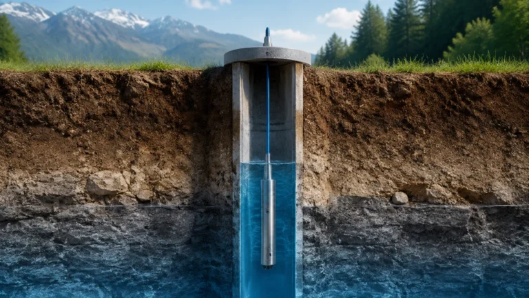
Q: How do I measure water level in a deep underground well?
A: Hydrostatic submersible transmitters are the standard for deep wells. They can be lowered hundreds of meters and provide stable readings regardless of the narrow diameter of the well casing.
Q: Does the salinity of the water affect the measurement?
A: For ultrasonic and radar sensors, salinity has no impact. For hydrostatic sensors, salinity increases the density of the water. Since hydrostatic pressure is density-dependent, the sensor must be calibrated for the specific gravity of the salt water to maintain accuracy.
Q: What is the benefit of 80GHz radar over 26GHz radar?
A: 80GHz radar has a much smaller wavelength, allowing for a smaller antenna and a tighter beam angle (often as narrow as 3°). This makes it much easier to install in tanks with internal obstacles or through small nozzles without interference.
Conclusion
Effective water level management is a cornerstone of modern industrial processing. By understanding the strengths and limitations of ultrasonic, radar, and hydrostatic technologies, engineers can specify a sensor water level system that provides years of maintenance-free service. For detailed product specifications and application-specific advice, professionals are encouraged to consult the technical resources available on the Main Page of Welk's industrial catalog. Whether the application involves a simple storage tank or a complex chemical reactor, selecting the right measurement principle is the first step toward process optimization.