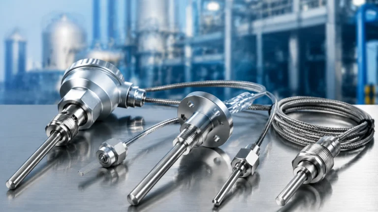
Electronic Flow Switch
Electronic Flow Switch
In modern industrial automation, the ability to monitor and control the movement of fluids within a piping system is fundamental to process safety and efficiency. An electronic flow switch serves as a critical monitoring device that detects the presence, absence, or rate of flow of a liquid or gas and triggers an electrical signal when specific thresholds are met. Unlike traditional mechanical flow switches that rely on moving parts like paddles or pistons, electronic variants utilize solid-state sensors to provide higher reliability, longer service life, and greater precision.
For engineers and plant managers, selecting the right instrumentation is essential for protecting expensive equipment such as pumps and heat exchangers. To explore a full range of industrial measurement solutions, you can visit the Main Page for detailed product specifications and application support.
Measurement Principles of Electronic Flow Switches
Electronic flow switches primarily operate on the principle of thermal dispersion, also known as the calorimetric principle. This method is favored in industrial B2B applications because it eliminates the wear and tear associated with mechanical components.
Thermal Dispersion (Calorimetric) Principle
A thermal electronic flow switch typically features two temperature sensors (thermistors) located within the tip of the probe that is inserted into the fluid stream.
1. The Reference Sensor: One sensor measures the actual ambient temperature of the medium.
2. The Heated Sensor: The second sensor is heated to a constant temperature difference relative to the reference sensor.
When the fluid is stationary, the heat remains concentrated around the heated sensor. As the fluid begins to flow, it carries heat away from the sensor—a process known as convective cooling. The electronics within the switch measure the power required to maintain the temperature differential or the change in temperature itself. Because the rate of heat loss is directly proportional to the flow velocity, the device can accurately determine when the flow has reached a predetermined setpoint.
Other Electronic Technologies
While thermal dispersion is the industry standard for "switches," other electronic methods include:
* Ultrasonic: Uses sound waves to detect flow velocity via the Doppler effect or transit-time measurement. These are often used for non-invasive switching.
* Electromagnetic: Utilizes Faraday’s Law of Induction to measure the flow of conductive liquids. These are highly accurate but limited to conductive media.
Key Advantages Over Mechanical Switches
Transitioning from mechanical to an electronic flow switch offers several technical benefits that reduce the Total Cost of Ownership (TCO) in industrial environments:
* No Moving Parts: Mechanical paddles can fatigue, clog with debris, or snap off in high-velocity streams. Electronic sensors are solid-state and resistant to mechanical failure.
* Low Pressure Drop: The probe of an electronic switch is typically small and streamlined, causing negligible resistance to the flow compared to a large mechanical paddle.
* High Sensitivity: Electronic switches can detect very low flow velocities (as low as 0.01 m/s) that would be insufficient to move a mechanical piston or paddle.
* Versatility: A single electronic unit can often be programmed for different flow ranges and media types, whereas a mechanical switch often requires a physical spring or paddle change.
Technical Selection Criteria
Selecting an electronic flow switch requires a detailed understanding of the process parameters. Use the following table as a baseline for evaluation:
| Parameter | Consideration | Impact on Selection |
| :— | :— | :— |
| Media Type | Liquid, gas, or slurry | Determines sensor coating and calibration. |
| Flow Velocity | Range in m/s | Thermal switches typically handle 0.03 to 3 m/s for liquids. |
| Pipe Diameter | DN15 to DN400+ | Influences probe length and insertion depth. |
| Operating Pressure | Bar (or PSI) | Standard units handle 100 bar; high-pressure versions are required for oil/gas. |
| Temperature Range | °C | Thermal switches must compensate for media temperature shifts. |
| Output Type | PNP, NPN, or Relay | Must be compatible with the PLC or control system. |
| Chemical Compatibility | Corrosive vs. Inert | Stainless steel (316L) is standard; Hastelloy or PTFE for acids. |
Installation Considerations
To ensure the accuracy and longevity of an electronic flow switch, proper installation is paramount. Incorrect placement is the leading cause of "nuisance tripping" or sensor failure.
Straight Pipe Requirements
Flow profiles must be stable for the sensor to provide a consistent reading. Turbulence caused by valves, elbows, or pumps can lead to erratic switching. A general engineering rule is the 5D/2D rule:
* Upstream: Provide at least 5 pipe diameters of straight, unobstructed pipe before the switch.
* Downstream: Provide at least 2 pipe diameters of straight pipe after the switch.
Orientation and Position
* Vertical Pipes: For liquid applications, the flow should ideally be upward to ensure the pipe is always full. If the flow is downward, air pockets may form, leading to false "no flow" signals.
* Horizontal Pipes: The switch should be installed on the side of the pipe (3 o'clock or 9 o'clock position). Installing on the top may lead to interference from air bubbles, while installing on the bottom may cause sediment to bury the sensor tip.
* Insertion Depth: The sensor tip should be located in the area of maximum flow velocity, typically the center of the pipe, to ensure the most accurate thermal transfer.
Limitations and Risks
While highly reliable, electronic flow switches are not universal solutions. Engineers should be aware of the following limitations:
1. Media Coating: If the fluid is highly viscous or prone to leaving deposits (like calcium scaling or heavy oils), a film can form over the sensor tip. This acts as an insulator, slowing the thermal response and causing the switch to become sluggish.
2. Aeration: Large air bubbles in a liquid stream can cause momentary drops in heat transfer, triggering false flow alarms. In such cases, an air eliminator should be installed upstream.
3. Rapid Temperature Fluctuations: Since thermal switches rely on temperature differentials, sudden, extreme changes in the media temperature (thermal shocks) can cause temporary inaccuracies until the reference sensor stabilizes.
Industrial Application Scenarios
1. Pump Dry-Run Protection
One of the most common uses for an electronic flow switch is protecting centrifugal pumps. If a pump runs without fluid, the internal seals and impellers can be destroyed by heat within minutes. A flow switch installed at the pump inlet or outlet can immediately shut down the motor if flow drops below a safe threshold.
2. Cooling Water Monitoring
In induction furnaces, welding machines, and large compressors, cooling water is essential to prevent equipment meltdown. Electronic switches provide a reliable interlock, ensuring the process only starts when cooling flow is confirmed.
3. Lubrication Systems
Large bearings in turbines and heavy machinery require a constant flow of lubricant. An electronic flow switch tuned for oil can detect even slight decreases in lubrication flow, allowing for predictive maintenance before a catastrophic bearing failure occurs.
Frequently Asked Questions (FAQ)
Q: Can an electronic flow switch be used for both liquids and gases?
A: Yes, many thermal dispersion switches are dual-purpose. However, they must be calibrated specifically for the medium because the thermal conductivity of gas is significantly lower than that of liquid.
Q: How do I calibrate the setpoint?
A: Most modern electronic switches feature a "teach-in" button or a digital display. You establish the desired flow rate in the system and then program the switch to recognize that specific thermal state as the "normal" condition.
Q: What maintenance is required?
A: Maintenance is minimal. Periodically checking the sensor tip for build-up or corrosion is recommended, especially in wastewater or chemical applications. If coating occurs, the tip can usually be cleaned with a soft cloth and a compatible solvent.
Q: Is there a difference between a flow switch and a flow meter?
A: Yes. A flow switch is a discrete device that provides a binary output (on/off) based on a setpoint. A flow meter provides a continuous measurement (e.g., 4-20mA or digital output) of the actual flow rate. Some electronic flow switches offer a basic trend display, but their primary function is switching.
Conclusion
The electronic flow switch represents a significant advancement in process monitoring technology. By leveraging the calorimetric principle, these devices offer a robust, maintenance-free alternative to mechanical switches, particularly in demanding B2B industrial environments. When selecting a unit, engineers must prioritize media compatibility, flow velocity, and proper installation geometry to ensure long-term operational success.
For technical assistance in choosing between radar, ultrasonic, or thermal measurement technologies for your specific facility, please refer to the extensive resources available on our Main Page.