Sump Level Switch
Sump Level Switch
In industrial fluid management, a sump level switch serves as a critical safety and automation component designed to monitor liquid levels in pits, tanks, and reservoirs. These devices are primarily used to prevent pump dry-running, mitigate overflow risks, and automate the drainage or filling processes in wastewater treatment, chemical processing, and industrial sumps. Selecting the correct technology requires a deep understanding of the physical principles of measurement, the chemical properties of the media, and the specific mechanical constraints of the installation site.
Understanding Sump Level Switch Measurement Principles
Before selecting a sump level switch, engineers must evaluate the underlying technology to ensure compatibility with the application. Several distinct physical principles govern how these switches detect the presence or absence of liquid.
Mechanical and Magnetic Float Principles
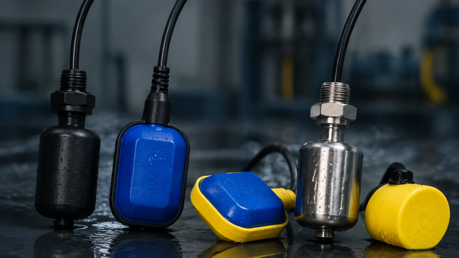
Mechanical float switches are the most common solution for sump applications. They operate on the principle of buoyancy. A float, typically made of polypropylene, stainless steel, or PVDF, rises and falls with the liquid level. In a basic mechanical setup, the movement of the float actuates a microswitch via a lever or a weighted cable.
Magnetic float switches, or reed switches, offer a more refined approach. A permanent magnet is housed within the float. As the float slides along a stem or pivots, the magnetic field closes or opens a hermetically sealed reed switch. This design is highly reliable because the electrical components are isolated from the process media.
Ultrasonic Point Level Detection
Ultrasonic switches use high-frequency sound waves to detect the liquid surface. The sensor emits an ultrasonic pulse that reflects off the liquid. For point level switching, these devices often use a "gap" technology where the signal is transmitted across a small space. When liquid fills the gap, the ultrasonic signal is attenuated or transmitted differently than when air is present, triggering the switch. This non-contact or low-contact method is ideal for corrosive or coating liquids.
Conductive Level Sensing
Conductivity switches are used for conductive liquids (typically water-based). They consist of electrodes (probes) cut to specific lengths. When the liquid reaches the probe, an electrical circuit is completed between the electrode and the tank wall (if metal) or a reference probe. This principle is extremely robust for sump applications but cannot be used with oils, distilled water, or non-conductive chemicals.
Capacitance Level Switching
Capacitance switches measure the change in electrical capacitance between two electrodes or between an electrode and the tank wall. As the liquid level changes, the dielectric constant in the surrounding area changes, altering the capacitance. This technology is versatile and can be calibrated to ignore foam or build-up on the probe, which is a common issue in industrial sumps.
Key Selection Criteria for Industrial Sumps
Choosing a sump level switch involves more than just selecting a technology; it requires matching the instrument to the environmental and process conditions. For comprehensive technical specifications and product ranges, engineers often consult a Main Page for industrial instrumentation to compare performance data.
1. Media Characteristics
* Viscosity: High-viscosity fluids can impede the movement of mechanical floats. In such cases, non-contact ultrasonic or heavy-duty capacitance switches are preferred.
* Corrosivity: For acidic or alkaline sumps, materials such as PVDF, PTFE, or high-grade stainless steel (316L) must be specified.
* Conductivity: If the liquid is non-conductive (e.g., fuel or oil), conductivity probes will not function.
2. Physical Environment
* Turbulence: Sumps with high inflow rates often experience surface turbulence. Mechanical switches may require a stilling well, or software-dampened ultrasonic sensors may be necessary.
* Foam and Vapor: Heavy foam can trigger ultrasonic sensors prematurely or insulate conductivity probes. Capacitance switches are generally better at "tuning out" foam.
* Temperature and Pressure: Most industrial sumps operate at atmospheric pressure, but temperature can vary. Standard polypropylene floats are usually rated up to 80°C, while stainless steel variants can handle over 150°C.
Comparison of Sump Level Switch Technologies
The following table provides a comparative overview of common switch types used in industrial sump applications.
| Technology | Best For | Advantages | Limitations |
| :— | :— | :— | :— |
| Cable Float | Wastewater, general drainage | Low cost, easy installation | Moving parts can foul; requires space for swing |
| Magnetic Float | Clean liquids, chemical tanks | High reliability, isolated electronics | Sensitive to magnetic particles; can clog in dirty media |
| Conductivity | Water, acids, bases | No moving parts, inexpensive | Requires conductive media; probe coating can cause failure |
| Ultrasonic | Corrosive liquids, non-contact | No contact with media, high accuracy | Affected by heavy foam and dense vapors |
| Capacitance | Slurries, coating liquids | Can ignore build-up, very robust | Requires calibration for specific media |
Installation and Engineering Best Practices
Proper installation is as critical as device selection. Failure to account for the physical layout of the sump can lead to premature device failure or inaccurate switching.
Mounting Positions
Switches should be mounted away from the direct path of the inflow pipe to avoid false triggers caused by splashing or liquid impact. For cable-hung float switches, ensure there is sufficient "tether length" to allow the float to pivot, but not so much that it can become entangled with pump hardware or the sump walls.
Stilling Wells
In sumps with significant agitation or turbulence, a stilling well (a vertical pipe with vent holes) should be installed. The level switch is then placed inside this pipe. This provides a calm liquid surface, ensuring the switch operates based on the true average level rather than surface waves.
Electrical Considerations
Most industrial sump level switches offer SPDT (Single Pole Double Throw) or DPDT (Double Pole Double Throw) relay outputs. It is essential to verify that the switch's electrical rating matches the control system (e.g., 24V DC for PLC inputs or 110V/230V AC for direct pump control). For hazardous areas, intrinsically safe barriers or explosion-proof housings must be utilized.
Common Risks and Operational Limitations
While a sump level switch is designed for durability, certain conditions can compromise performance:
1. Material Build-up: In wastewater applications, fats, oils, and grease (FOG) can accumulate on floats or probes. This increases the weight of floats or creates conductive bridges on probes, leading to "stuck" signals. Regular cleaning cycles should be factored into maintenance schedules.
2. Mechanical Fatigue: For cable-suspended switches, the constant flexing of the cable at the entry point can lead to internal wire breakage over several years. High-quality polyurethane or Neoprene cables are recommended for longevity.
3. Specific Gravity Changes: Float switches are designed for specific liquid densities (usually based on water, SG = 1.0). If the liquid density drops significantly (e.g., to 0.7 for certain hydrocarbons), the float may not remain buoyant enough to actuate the switch.
Frequently Asked Questions (FAQs)
Q: Can I use a single switch to start and stop a pump?
A: A single point level switch can only indicate one level. To start and stop a pump (differential control), you typically need two switches (high and low) or a specialized dual-point float switch with a built-in hysteresis or latching relay.
Q: How often should a sump level switch be calibrated?
A: Mechanical float switches and conductivity probes generally do not require calibration. However, ultrasonic and capacitance switches should be verified annually or whenever the process media changes significantly.
Q: What is the difference between N/O and N/C contacts in this context?
A: N/O (Normally Open) means the circuit is open when the switch is in its "natural" state (usually dry). N/C (Normally Closed) means the circuit is complete when dry. For high-level alarms, N/C is often preferred for fail-safe operation, as a wire break will trigger the alarm.
Q: Are there switches suitable for sumps containing flammable liquids?
A: Yes. In these environments, you must use ATEX or IECEx certified explosion-proof switches or intrinsically safe systems where the energy levels are limited to prevent ignition.
Conclusion
Selecting a sump level switch requires a balanced evaluation of technology, media compatibility, and installation environment. Whether utilizing the simplicity of a buoyant float or the sophistication of ultrasonic detection, the goal remains the same: reliable, repeatable point-level monitoring. For engineers seeking specific model dimensions, wiring diagrams, or material compatibility charts, visiting the Main Page of a dedicated industrial manufacturer is the recommended next step to ensure the chosen solution meets the rigorous demands of industrial automation.