Tank High Level Alarm
Tank High Level Alarm
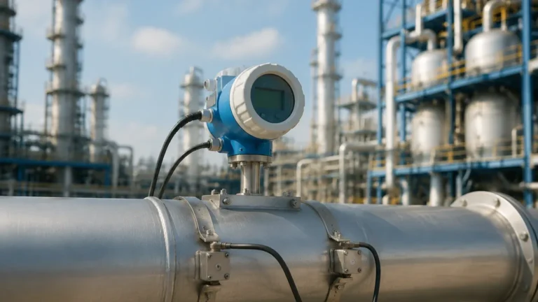
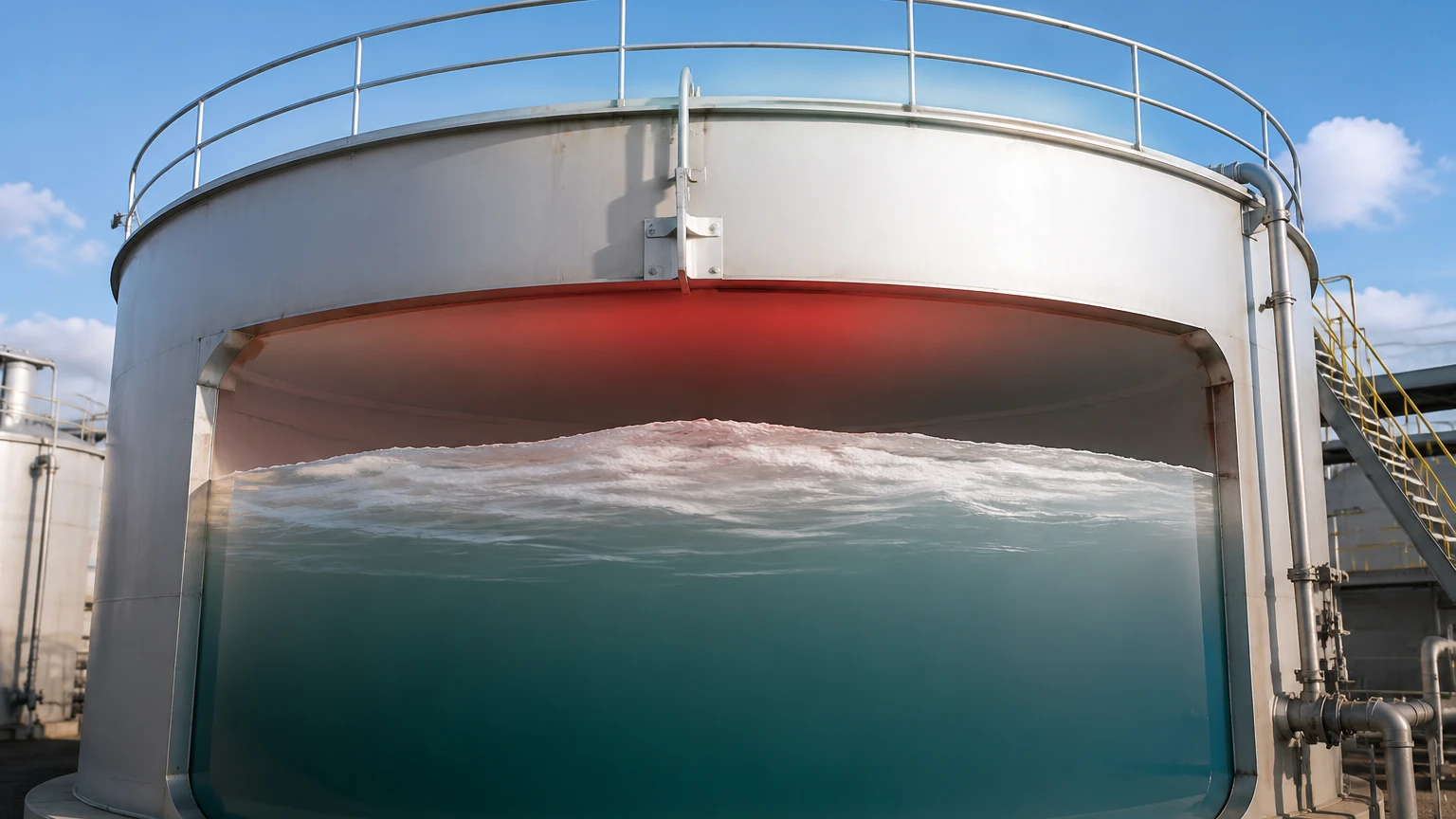
In industrial process control, the implementation of a tank high level alarm is a fundamental safety and operational requirement. Whether managing water treatment facilities, chemical processing plants, or oil and gas storage, the ability to detect when a vessel has reached its maximum safe capacity is critical for preventing environmental contamination, equipment damage, and hazardous material spills. A tank high level alarm serves as the final line of defense or a primary control point to trigger automated shut-off valves, sound audible alerts, or initiate emergency protocols.
Selecting the appropriate technology for high-level detection requires an understanding of the physical properties of the media, the environmental conditions within the tank, and the specific safety integrity levels required by the application. This guide examines the measurement principles, technology options, and engineering considerations necessary for deploying reliable high-level alarm systems.
Measurement Principles for High-Level Detection
High-level detection generally falls into two categories: point level detection and continuous level monitoring with integrated alarm logic.
Point Level Detection
Point level detection utilizes a dedicated switch located at a specific height (the "high-point") within the tank. When the material—liquid or solid—reaches this sensor, it triggers a state change in the output (e.g., from normally open to normally closed). This is the most common method for a dedicated tank high level alarm because it is mechanically or electronically independent of the primary level control system, providing a layer of redundancy.
Continuous Level Monitoring
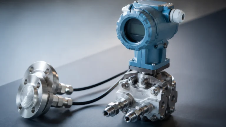
Continuous level sensors, such as radar or ultrasonic transmitters, provide a constant data stream of the current level. High-level alarms are programmed into the control system (PLC/DCS) or the transmitter itself based on the measured distance. While this allows for adjustable alarm setpoints, safety standards often recommend a separate point level switch to act as a redundant high-high alarm in case the continuous transmitter fails or loses signal.
Core Technologies for Tank High Level Alarms
1. Vibrating Tuning Fork Switches
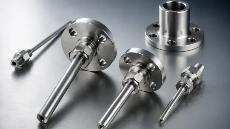
Vibrating level switches utilize a tuning fork-shaped element driven by piezoelectric crystals to vibrate at their natural resonant frequency (typically around 1,200 Hz). When the liquid media covers the fork, the frequency drops significantly due to the increased density of the surrounding medium. The internal electronics detect this frequency shift and trigger the alarm output.
* Advantages: Not affected by bubbles, foam, or vibration. Requires no calibration.
* Limitations: Not suitable for extremely viscous liquids that may cause "bridging" between the forks.
2. Ultrasonic Level Sensors
Ultrasonic sensors operate on the Time-of-Flight (ToF) principle. The sensor emits a high-frequency sound pulse (usually 40 kHz to 70 kHz) that travels through the air, reflects off the liquid surface, and returns to the transducer. The time taken for this transit is proportional to the distance.
* Advantages: Non-contact measurement, ideal for corrosive liquids.
* Limitations: Performance can be degraded by heavy foam, steam, or vacuum conditions. It is essential to account for the "blocking distance" (dead zone) near the sensor face.
3. Radar Level Meters
Radar level meters, particularly 80 GHz FMCW (Frequency Modulated Continuous Wave) models, emit high-frequency microwave signals. Like ultrasonic sensors, they use ToF or frequency shifts to determine distance. However, microwaves are not affected by air temperature, pressure, or vapor layers.
* Advantages: Highly accurate (up to ±1 mm), works in vacuums and high-pressure environments.
* Limitations: Higher initial cost compared to simple switches.
4. Float Level Switches
This is the most traditional mechanical method. A float containing a magnet moves along a stem as the liquid rises. When the float reaches a reed switch embedded in the stem, the magnetic field closes the circuit. For external mounting, magnetic level gauges use a similar principle where a float in a bypass chamber triggers external switch modules.
* Advantages: Simple, low cost, and requires no power for the basic switch mechanism.
* Limitations: Moving parts are susceptible to fouling or sticking if the liquid contains solids or scales.
Selection Criteria for Industrial Applications
Choosing the right tank high level alarm involves evaluating several technical parameters. For a detailed comparison of specific instrument models, engineers should consult the Main Page to review product options and application support.
Media Characteristics
* Viscosity: High-viscosity fluids may require non-contact radar or heavy-duty displacement floats.
* Corrosivity: Corrosive acids require PTFE or PVDF coated sensors.
* Dielectric Constant: For radar and capacitance switches, the dielectric constant ($ε_r$) of the liquid determines the signal reflection strength.
Tank Environment
* Pressure and Temperature: Ensure the sensor housing and wetted parts can withstand the maximum operating pressure (e.g., 40 bar / 580 psi) and temperature (e.g., 150°C / 302°F).
* Turbulence: If the tank has an agitator, a tuning fork or a radar with sophisticated signal processing is preferred over a mechanical float.
Summary Selection Table
| Technology | Media Type | Best For | Limitations |
| :— | :— | :— | :— |
| Tuning Fork | Liquids/Slurries | Redundant safety alarm | Viscous buildup |
| Ultrasonic | Water/Chemicals | Non-contact, budget-friendly | Foam, steam, vacuum |
| Radar (80GHz) | All Liquids | High precision, harsh vapors | Higher cost |
| Float Switch | Clean Liquids | Simple pump control | Moving parts can jam |
| Capacitance | Solids/Liquids | High temperature/pressure | Requires calibration |
Installation and Engineering Considerations
Correct installation is as vital as technology selection for a functional tank high level alarm. Failure to follow installation guidelines often leads to false positives or, worse, a failure to trip during an overfill.
Mounting Position
The sensor should be mounted away from the tank inlet to avoid interference from the incoming flow stream. For non-contact sensors like radar or ultrasonic, the beam must have a clear path to the liquid surface, free from internal obstructions like ladders, heating coils, or stay braces.
Nozzle Design
When using nozzle mounting, the nozzle diameter and length must be considered. If a nozzle is too long and narrow, it can create "ringing" or false reflections for ultrasonic and radar sensors. For tuning fork switches, the forks must extend fully into the tank beyond the nozzle to ensure the liquid can flow freely around them.
Wiring and Integration
* Fail-Safe Logic: High-level alarms should be wired in a "fail-safe" configuration. This typically means the relay is energized when the level is low (safe) and de-energizes when the level is high or if power is lost. This ensures that a broken wire is detected as an alarm state.
* Cable Routing: Use shielded cables for electronic sensors to prevent EMI (Electromagnetic Interference) from nearby pumps or motors.
Common Risks and Limitations
Despite advanced technology, certain factors can compromise a tank high level alarm:
1. Product Buildup: In sticky or crystallizing media, material can accumulate on the sensor. While some radar and tuning fork models have "build-up compensation," extreme coating will eventually cause a malfunction.
2. Foam Interference: Heavy, dense foam can absorb ultrasonic signals or be misidentified by radar as the actual liquid level. In such cases, a bypass pipe or a contact-based vibrating switch is more reliable.
3. Dead Zones: Every non-contact sensor has a minimum distance (dead zone) it cannot measure. If the high-level alarm point is set within this zone, the sensor will fail to detect the rising liquid.
4. Gas Layers: In chemical tanks, heavy vapors or gas blankets (like Nitrogen) can change the speed of sound, affecting ultrasonic accuracy. Radar is generally immune to this.
Frequently Asked Questions (FAQ)
Q: Should I use a continuous sensor or a point switch for a high-level alarm?
A: For critical safety applications, it is best practice to use both. Use a continuous sensor (radar/ultrasonic) for operational control and a separate, independent point level switch (tuning fork/float) for the high-high emergency alarm.
Q: How do I test a tank high level alarm without filling the tank?
A: Many modern electronic switches, such as Welk tuning forks, include a test magnet or a manual test button that simulates a frequency shift. For radar, a "loop test" can be performed via the HART protocol to verify the output signal.
Q: Can a high-level alarm be used in explosive atmospheres?
A: Yes, but the instrument must be certified (e.g., ATEX, IECEx, or Ex-proof). Intrinsically safe (IS) versions limit the energy available to prevent ignition, while flameproof versions contain any internal explosion.
Q: What is the recommended maintenance schedule?
A: At a minimum, a functional "proof test" should be conducted annually. This involves physically raising the level or manually triggering the sensor to ensure the entire alarm chain—from sensor to siren or valve—operates correctly.
Conclusion
Implementing a robust tank high level alarm system is an essential investment in industrial safety and efficiency. By understanding the measurement principles of tuning forks, radar, and ultrasonic technologies, engineers can select the solution that best fits their specific media and environmental constraints. Proper installation, fail-safe wiring, and regular maintenance ensure these systems provide the necessary protection against overfill incidents. For more information on selecting the right instrumentation for your facility, visit the Main Page to explore our full range of level measurement solutions.