Ultrasonic Meter Principle
Ultrasonic Meter Principle: A Comprehensive Guide to Non-Contact Level Measurement
In the realm of industrial process control, accurate level measurement is essential for operational efficiency, safety, and inventory management. Among the various technologies available, Ultrasonic Level Meters have emerged as a preferred solution for many liquid and solid applications due to their non-contact nature and cost-effectiveness. Understanding the underlying ultrasonic meter principle is critical for engineers and plant managers to ensure correct instrument selection and reliable long-term performance.
This article provides a technical overview of how ultrasonic technology functions, its practical applications, and the engineering considerations necessary for successful implementation in B2B environments such as water treatment, chemical processing, and industrial automation.
Understanding the Ultrasonic Meter Principle
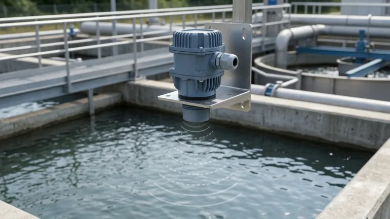
The core of the ultrasonic meter principle is based on the "Time-of-Flight" (ToF) measurement of sound waves. Unlike contact-based methods such as float switches or pressure transmitters, ultrasonic sensors operate by emitting high-frequency acoustic pulses that travel through the air to the surface of the medium being measured.
The Measurement Cycle
1. Emission: A piezoelectric crystal within the transducer converts electrical energy into mechanical energy, producing a burst of ultrasonic sound waves (typically between 20 kHz and 200 kHz).
2. Propagation: These sound waves travel through the air gap between the sensor and the material surface.
3. Reflection: Upon hitting the surface of the liquid or solid, the sound waves are reflected back toward the sensor as an echo.
4. Reception: The transducer receives the returning echo and converts the mechanical vibration back into an electrical signal.
5. Calculation: The internal electronics measure the time elapsed between the emission and the reception. Since the speed of sound in air is known, the distance to the surface can be calculated using the following formula:
D = (c × t) / 2
Where:
* D is the distance from the sensor to the material surface.
* c is the speed of sound in the medium (typically air).
* t is the total time elapsed (the "Time-of-Flight").
By subtracting this distance from the total height of the vessel (the "Empty Distance"), the meter determines the actual level of the material.
Speed of Sound and Temperature Compensation
A critical factor in the ultrasonic meter principle is that the speed of sound is not constant; it varies primarily with the temperature of the air through which it travels. For instance, at 0°C (32°F), the speed of sound is approximately 331.5 m/s, while at 20°C (68°F), it increases to about 343 m/s. To maintain accuracy, modern Ultrasonic Level Meters include integrated temperature sensors to automatically compensate for these fluctuations in real-time.
Key Components of Ultrasonic Level Meters
To implement the ultrasonic meter principle effectively, the instrument consists of several integrated components designed to withstand industrial environments:
* Transducer: The "heart" of the device, containing the piezoelectric elements. It acts as both a transmitter and a receiver.
* Signal Processor: Advanced electronics that filter out noise and false echoes (such as those from tank agitators or internal ladders) to identify the true surface reflection.
* Housing: Usually constructed from materials like PVDF, PP, or stainless steel to provide chemical resistance and ingress protection (IP65 to IP68).
* Display and Interface: Allows for local calibration, level visualization, and output configuration (e.g., 4-20mA, HART, or Modbus RS485).
Selecting the Right Ultrasonic Level Meter
Choosing the correct instrument requires an evaluation of the process environment and the material properties. The following table provides a general guide for selecting ultrasonic sensors based on common industrial requirements.
Selection Table: Ultrasonic Level Meter Specifications
| Feature | Standard Liquid Application | Solids/Powder Application | Harsh Chemical Application |
| :— | :— | :— | :— |
| Measurement Range | 0.3m to 15m (1ft to 49ft) | 0.5m to 10m (1.6ft to 33ft) | 0.3m to 10m (1ft to 33ft) |
| Transducer Material | ABS / PVC | Reinforced Polymer | PVDF / PTFE |
| Beam Angle | 6° to 12° | 5° to 8° (Narrower) | 9° to 12° |
| Accuracy | ±0.25% to 0.5% of range | ±1% of range | ±0.5% of range |
| Output Signal | 4-20mA / HART | 4-20mA / RS485 | 4-20mA / HART |
| Pressure Rating | Atmospheric | Atmospheric | Up to 3 bar (43 psi) |
Installation Best Practices and Considerations
Even the most advanced sensor will fail if the installation does not respect the physics of the ultrasonic meter principle. Engineers must follow these guidelines to ensure reliable data:
1. The Blocking Distance (Dead Zone)
Every ultrasonic sensor has a "blocking distance" or "dead zone" directly beneath the transducer face (typically 0.2m to 0.5m). Within this zone, the sensor cannot receive echoes because it is still vibrating from the emission pulse. The sensor must be mounted high enough so that the maximum liquid level never enters this dead zone.
2. Beam Path Obstructions
The ultrasonic pulse spreads out in a cone shape (the beam angle). If the beam hits internal tank structures like pipes, ladders, or agitators, it will create false echoes. The sensor should be positioned away from the tank wall and internal obstacles.
3. Surface Conditions
Ultrasonic waves reflect best off smooth, flat surfaces. If the liquid surface is turbulent or covered in thick foam, the sound waves may be scattered or absorbed, leading to signal loss. In such cases, a stilling well may be required to provide a calm surface for measurement.
4. Mounting Orientation
The transducer face must be mounted perfectly perpendicular to the surface of the medium. If the sensor is tilted, the reflected echo may not return to the receiver, resulting in an "Echo Loss" error.
Limitations and Environmental Factors
While the ultrasonic meter principle is versatile, certain conditions can limit its effectiveness. Understanding these boundaries prevents misapplication:
* Vacuum Conditions: Sound waves require a medium (gas/air) to travel. Ultrasonic meters cannot function in a vacuum.
* High Pressure: High-pressure environments change the density of the air, significantly affecting the speed of sound and signal attenuation. Most standard ultrasonic meters are limited to near-atmospheric pressures.
* Heavy Dust or Steam: In applications like cement silos or boiling tanks, heavy dust or dense steam can absorb the acoustic energy, reducing the effective range of the sensor.
* Temperature Extremes: While compensation handles air temperature changes, extreme heat (above 80°C / 176°F) can damage the transducer or create significant temperature gradients that make accurate compensation difficult.
Frequently Asked Questions (FAQ)
Q: Can ultrasonic level meters be used for solids like grain or sand?
A: Yes, but with caveats. Solids often have an angle of repose that scatters the sound waves. For solids, it is recommended to use a sensor with a higher power output and a narrower beam angle to ensure a strong return signal.
Q: How does foam affect the measurement?
A: Light, airy foam can absorb the ultrasonic signal, causing the meter to lose the echo. Dense, thick foam might reflect the signal, but the meter will measure the top of the foam rather than the liquid level. For heavy foam applications, a radar level meter or a hydrostatic transmitter might be more appropriate.
Q: What is the difference between an ultrasonic level transmitter and a level switch?
A: An ultrasonic level meter (or transmitter) provides continuous measurement (e.g., 0-100% level), whereas an ultrasonic level switch only detects the presence of material at a specific point (High or Low alarm).
Q: Is maintenance required for these sensors?
A: Because they are non-contact, maintenance is minimal. However, in applications with high humidity or splashing, users should periodically check the transducer face for condensation or material buildup, which can interfere with signal emission.
Conclusion
The ultrasonic meter principle provides a robust and non-invasive way to monitor levels across a wide variety of industrial tanks and open channels. By leveraging the Time-of-Flight method and accounting for environmental variables like temperature and beam obstruction, Welk's measurement solutions deliver the accuracy required for modern process automation. When selecting a device, always consider the specific properties of your medium and the physical constraints of your installation site to maximize the reliability of your level measurement system.