Ultrasonic Level Sensor Mounting
Ultrasonic Level Sensor Mounting: A Comprehensive Engineering Guide
In industrial process control, the accuracy of level measurement is often determined long before the first signal is processed. For non-contact technologies, the physical interface between the instrument and the vessel is the most critical factor in system performance. Proper ultrasonic level sensor mounting ensures that the acoustic signal travels unimpeded to the material surface and returns with sufficient strength to provide a reliable reading.
As a professional manufacturer, Welk emphasizes that even the most advanced Ultrasonic Level Meters can fail to perform if installation best practices are ignored. This guide provides a detailed technical overview of mounting principles, common challenges, and practical selection criteria for engineering professionals.
Understanding the Principle of Ultrasonic Level Measurement
Before addressing mounting configurations, it is essential to understand how these instruments operate. Ultrasonic level sensors utilize a piezoelectric transducer to emit high-frequency sound waves, typically in the range of 20 kHz to 200 kHz. These waves travel through the air medium, reflect off the surface of the liquid or solid, and return to the transducer.
The device measures the "Time of Flight" (ToF)—the duration between the pulse emission and the echo reception. The distance ($D$) is calculated using the formula:
$$D = \frac{c \times t}{2}$$
Where:
* $c$ is the speed of sound in the medium (adjusted for temperature).
* $t$ is the measured time.
Because the speed of sound is affected by air temperature, most high-quality ultrasonic level meters include an integrated temperature sensor to compensate for these fluctuations. However, the physical mounting of the sensor dictates the path the sound wave takes. If the sensor is tilted or obscured, the echo may be lost or distorted, leading to "lost echo" errors or false readings.
The Critical Role of Proper Ultrasonic Level Sensor Mounting
Mounting is not merely about securing the device to a tank; it is about managing the "acoustic environment." Sound waves do not travel in a laser-straight line; they propagate in a cone shape, known as the beam angle. Anything that enters this cone—such as tank walls, ladders, or agitators—can create a false reflection.
1. Vertical Alignment
The transducer face must be mounted perfectly parallel to the liquid surface. If the sensor is tilted by even a few degrees, the sound wave may reflect off the surface at an angle and fail to return to the receiver. For solids measurement, where the material forms a conical pile, adjustable mounting flanges are often used to aim the sensor at a specific point on the slope to optimize signal return.
2. Distance from the Tank Wall
A common rule of thumb in industrial engineering is to mount the sensor at a distance from the wall equal to at least 1/6th of the tank's diameter. Mounting too close to the wall can lead to interference from the wall itself or from buildup on the vessel sides, which can scatter the signal.
3. Avoiding the Center of Domed Tanks
For tanks with parabolic or domed tops, mounting the sensor in the exact center should be avoided. The curved geometry of the roof can act as a parabolic reflector, focusing multiple echoes back to the sensor and causing erratic readings. Off-center mounting is the standard solution for these vessel types.
Managing the "Dead Zone" (Blocking Distance)
Every ultrasonic sensor has a "dead zone" or "blocking distance" directly beneath the transducer face. This is a region where the sensor cannot accurately measure because the transducer is still vibrating from the pulse emission when the echo returns.
Typically, the dead zone ranges from 0.2 meters to 0.8 meters (approximately 8 to 31 inches), depending on the frequency of the sensor. If the liquid level enters this zone, the sensor will provide an incorrect reading or go into an error state.
To mitigate this, engineers often use standpipes or nozzles to raise the sensor higher above the maximum liquid level. When using a standpipe, the interior must be smooth and free of burrs or welds to prevent internal reflections.
Ultrasonic Level Sensor Mounting in Challenging Environments
Industrial applications rarely present ideal conditions. Mounting strategies must adapt to the specific physical properties of the process.
Obstructions and False Echoes
Internal structures like heating coils, ladders, or support struts are common. Modern ultrasonic level meters feature "False Echo Suppression" or "Echo Mapping" software. During commissioning, the sensor scans the empty tank and records the positions of fixed obstructions. It then ignores reflections from these distances, focusing only on the moving surface. However, physical clearance is always preferred over software filtering.
Turbulence and Foam
Inflow pipes should never be located directly under the sensor. The turbulence and splashing create an unstable surface that scatters the acoustic signal. Furthermore, heavy foam can absorb ultrasonic waves entirely. In such cases, mounting the sensor inside a stilling well (a vertical pipe with vent holes) can provide a calm surface for measurement, though the pipe diameter must be sufficient to avoid signal interference.
Outdoor and High-Humidity Installations
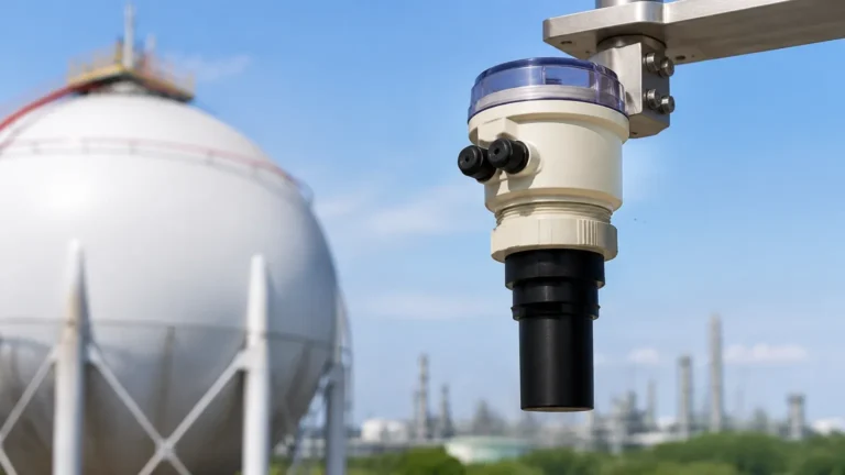
Condensation on the transducer face can attenuate the signal. Many sensors are designed with a self-cleaning effect through vibration, but mounting the sensor in a way that allows moisture to drip off (avoiding recessed pockets) is beneficial. For outdoor use, a sunshade is recommended to prevent the integrated temperature sensor from being skewed by direct solar heating.
Practical Selection and Mounting Table
Choosing the right mounting hardware depends on the vessel type and the chemical compatibility of the process.
| Mounting Type | Best For | Advantages | Limitations |
| :— | :— | :— | :— |
| Threaded (NPT/G) | Small tanks, plastic sumps | Cost-effective, easy to install | Limited pressure rating; requires a threaded boss |
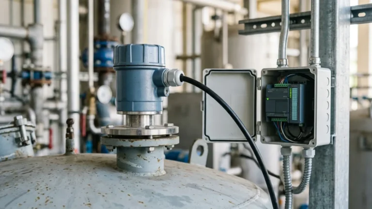
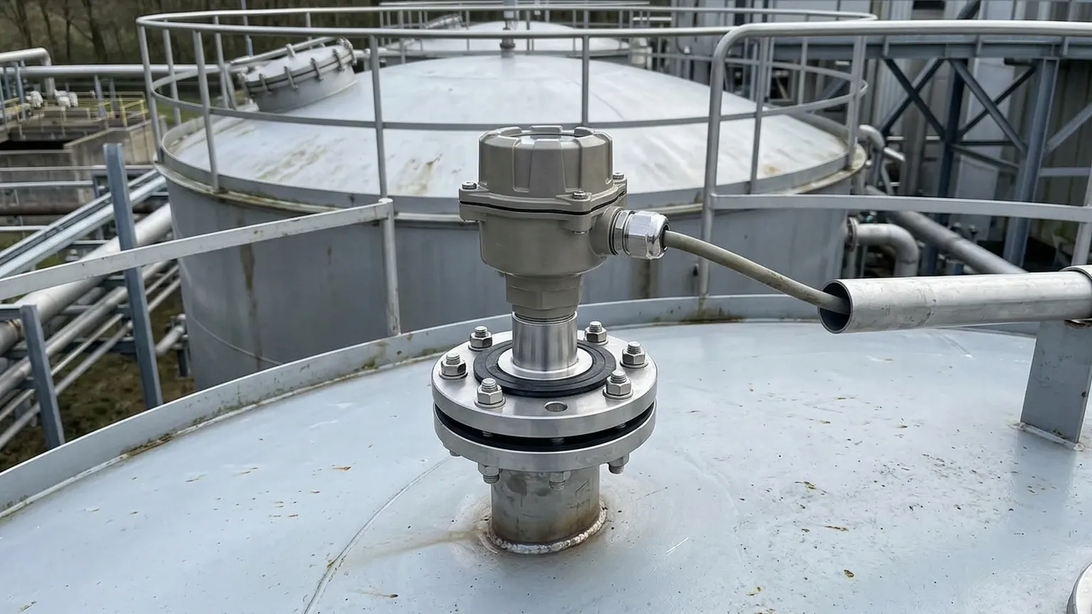
| Flanged (ANSI/DIN) | Chemical reactors, pressurized vessels | High pressure/temp resistance; very secure | Higher cost; requires matching flange on tank |
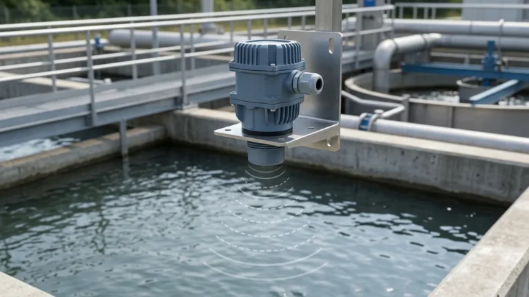
| Bracket/Submersible | Open channels, reservoirs, wet wells | Flexible positioning; easy maintenance | Not suitable for pressurized environments |
| Standpipe/Nozzle | Avoiding the dead zone; high tanks | Allows measurement to the very top of the tank | Requires careful internal smoothing to avoid echoes |
Step-by-Step Installation Checklist
To ensure a successful deployment, follow this systematic approach to ultrasonic level sensor mounting:
1. Verify the Range: Ensure the distance from the sensor face to the tank bottom is within the instrument's maximum range, and the maximum liquid level remains below the dead zone.
2. Check the Beam Angle: Calculate the beam diameter at the bottom of the tank. Ensure no obstructions (ladders, pipes) are within this cone.
3. Positioning: Locate the sensor away from the fill inlet to avoid turbulence and away from the tank wall (1/6th diameter rule).
4. Mechanical Installation:
* For threaded mounts, use appropriate sealant (e.g., PTFE tape).
* For flanged mounts, ensure the gasket is compatible with the process fluid.
* Ensure the sensor is perfectly vertical.
5. Electrical Connection: Use shielded cables to prevent EMI/RFI interference from nearby motors or VFDs. Ensure the cable entry points are sealed with glands to prevent moisture ingress.
6. Commissioning: Perform a "dry run" with an empty tank to map false echoes. Calibrate the 4-20mA or digital output against manual tape measurements at multiple points.
Frequently Asked Questions (FAQs)
Q: Can I mount an ultrasonic sensor at an angle to measure a slope?
A: Generally, no. The sensor should be perpendicular to the surface. However, for bulk solids, an adjustable flange can be used to find the angle that provides the strongest return signal from the material's angle of repose.
Q: How do I handle heavy condensation on the sensor face?
A: Some sensors feature a parabolic or curved face to encourage droplets to run off. Additionally, mounting the sensor slightly higher in a heated nozzle can sometimes reduce the temperature differential that causes condensation.
Q: What is the maximum nozzle length for mounting?
A: The nozzle should be as short and wide as possible. If the nozzle is too long or narrow, the sensor will detect the end of the nozzle as a target. As a rule, the nozzle diameter should increase as the length increases (e.g., a 100mm long nozzle should be at least 50mm in diameter).
Q: Can ultrasonic sensors work in a vacuum?
A: No. Ultrasonic waves require a medium (air or gas) to travel. In a vacuum, there are no molecules to transmit the sound energy. For vacuum applications, radar level meters are the preferred technology.
Conclusion
Precision in level measurement is a product of both high-quality instrumentation and rigorous installation standards. By adhering to the principles of verticality, clearance, and dead-zone management, engineers can maximize the reliability of their systems. Whether dealing with water treatment, chemical storage, or industrial automation, the correct approach to ultrasonic level sensor mounting is the foundation of process safety and efficiency.
For more technical specifications and to explore various sensor configurations, you can Review product options and application support to find the right fit for your specific industrial requirements.