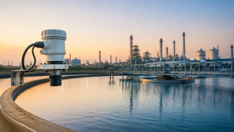
Ultrasonic Level Sensor PDF
Ultrasonic Level Sensor PDF
In industrial process control, selecting the correct instrumentation requires a deep dive into technical specifications, often found in a comprehensive ultrasonic level sensor pdf. These documents serve as the primary reference for engineers and system integrators, providing the necessary data on beam angles, frequency ranges, and environmental tolerances. For manufacturers like Welk, providing clear, factual data is essential for ensuring that Ultrasonic Level Meters are applied correctly across water treatment, chemical processing, and industrial automation sectors.
This guide explores the fundamental principles of ultrasonic technology, the critical data points found in technical documentation, and the practical considerations for successful installation and operation.
Understanding the Measurement Principle
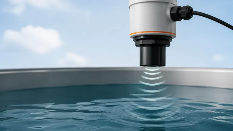
Ultrasonic level measurement is a non-contact technology based on the "Time-of-Flight" (ToF) principle. The instrument’s transducer acts as both a transmitter and a receiver. It emits a series of high-frequency sound pulses—typically ranging from 20 kHz to over 70 kHz—that travel through the air toward the surface of the material being measured.
When the sound wave hits the surface of the liquid or solid, it is reflected back to the transducer. The sensor’s internal electronics measure the time interval between the emission of the pulse and the reception of the echo. Since the speed of sound in air is a known constant (approximately 343 m/s at 20°C), the distance to the surface can be calculated using the following formula:
Distance = (Speed of Sound × Time Delay) / 2
The level of the material is then determined by subtracting this distance from the total height of the vessel (the calibration distance).
The Role of Temperature Compensation
One of the most critical sections in any ultrasonic level sensor pdf is the specification for temperature compensation. Because the speed of sound varies with air temperature—increasing by approximately 0.6 m/s for every degree Celsius increase—accurate measurement requires an integrated temperature sensor. This sensor allows the meter to adjust its calculations in real-time to maintain accuracy despite shifting environmental conditions.
Key Technical Specifications in an Ultrasonic Level Sensor PDF
When evaluating a datasheet or technical manual, several parameters dictate whether a specific model is suitable for an application. Engineers must verify these boundaries before procurement.
1. Measuring Range and Dead Zone
Every ultrasonic sensor has a minimum and maximum range. The "Dead Zone" (or Near-Field) is the area directly beneath the transducer face where the sensor cannot accurately process echoes because the pulse has not yet finished transmitting when the reflection returns. Typical dead zones range from 0.25m to 0.5m (approx. 10 to 20 inches). If the liquid level enters this zone, the output will become erratic or lock at the maximum value.
2. Beam Angle and Frequency
The beam angle defines the spread of the ultrasonic pulse. A narrower beam angle (e.g., 5° to 8°) is generally preferred for tall, narrow tanks or vessels with internal obstructions like ladders or agitators. Higher frequency sensors typically offer narrower beam angles and better resolution but have a shorter effective range due to faster signal attenuation in the air.
3. Output and Communication Protocols
Modern industrial systems require seamless integration. Standard specifications usually include:
* Analog Output: 4-20mA (often loop-powered).
* Digital Communication: RS485 (Modbus RTU), HART, or Profibus.
* Switching: Integrated relays for high/low-level alarms.
4. Material Compatibility
The transducer face is the only part of the instrument exposed to the tank atmosphere. Common materials include PVDF (Polyvinylidene fluoride) for corrosive chemicals, or PU (Polyurethane) for general water applications. A technical ultrasonic level sensor pdf will list the chemical resistance of these materials to ensure longevity in harsh environments.
Practical Selection Table
| Parameter | Standard Industrial Grade | High-Performance Grade |
| :— | :— | :— |
| Measuring Range | 0.3m – 10m | 0.5m – 30m |
| Accuracy | ±0.5% of Full Scale | ±0.2% of Full Scale |
| Resolution | 3 mm | 1 mm |
| Beam Angle | 10° – 12° | 5° – 8° |
| Pressure Limit | Up to 2 bar (29 psi) | Up to 3 bar (43.5 psi) |
| Temperature Range | -20°C to +60°C | -40°C to +80°C |
Installation Considerations and Best Practices
Proper installation is the single most important factor in the reliability of Ultrasonic Level Meters. Even the most advanced sensor will fail if the physical setup ignores the physics of sound propagation.
Mounting Position
* Avoid the Center: In cylindrical tanks with domed tops, mounting the sensor in the exact center can create a "parabolic" effect, where multiple reflections converge and confuse the electronics.
* Perpendicularity: The transducer face must be perfectly parallel to the liquid surface. A tilt of even a few degrees can cause the echo to bounce away from the sensor rather than back to it.
* Distance from Wall: To avoid interference from wall echoes or buildup on the tank sides, the sensor should be placed at least 1/6th of the tank diameter away from the wall.
Managing Obstructions
Internal structures like heating coils, pump supports, or agitator blades can generate "false echoes." While many modern sensors include software for "False Echo Suppression" (allowing the user to map out and ignore specific static reflections), it is always better to install the sensor in a clear path to the liquid.
Nozzle Geometry
If the sensor is mounted on a standpipe or nozzle, the height and diameter of the nozzle must be checked against the sensor’s beam angle. If the nozzle is too narrow or too long, the ultrasonic pulse will hit the nozzle walls, creating a massive false echo that prevents the sensor from seeing the actual level.

Limitations and Environmental Factors
While ultrasonic technology is versatile and cost-effective, it is not a universal solution. Engineers must recognize the following limitations:
1. Vacuum Conditions: Sound requires a medium (air or gas) to travel. Ultrasonic sensors cannot function in a vacuum.
2. Heavy Foam: Thick, aerated foam on the surface of a liquid acts as an acoustic insulator, absorbing the sound pulse rather than reflecting it. In these cases, radar or hydrostatic sensors are often preferred.
3. High Pressure/Density: Significant changes in tank pressure alter the density of the gas through which the sound travels, which can change the speed of sound beyond what standard temperature compensation can correct.
4. Heavy Dust or Vapor: While light dust is manageable, extremely dense dust (in powder silos) or heavy steam can scatter the signal, reducing the effective range of the instrument.
Maintenance and Troubleshooting
Ultrasonic sensors are generally low-maintenance because they have no moving parts and do not touch the process media. However, certain conditions require periodic checks:
* Condensation: In high-humidity applications, water droplets can form on the transducer face. While many sensors are designed to shed moisture, excessive buildup can attenuate the signal. Some sensors use a "self-cleaning" vibration to shake off droplets.
* Transducer Scaling: In chemical applications, fumes may crystallize on the sensor face. This should be cleaned with a soft cloth and appropriate solvent to maintain signal integrity.
Common Troubleshooting Steps
* Loss of Echo: Check for foam, check if the level is in the dead zone, or verify if the transducer is perpendicular to the surface.
* Unstable Reading: This is often caused by surface turbulence or agitator interference. Increasing the damping (averaging) time in the sensor settings can often smooth out the output.
Frequently Asked Questions (FAQs)
Q: Can I use an ultrasonic level sensor for solids?
A: Yes, but with caution. Solids like grain or plastic pellets often form a conical pile rather than a flat surface. This scatters the sound wave. For solids, it is recommended to use a sensor with a higher power output and a lower frequency to compensate for the uneven reflection.
Q: What is the difference between a two-wire and a four-wire sensor?
A: A two-wire (loop-powered) sensor uses the same two wires for both power supply and the 4-20mA signal. It is easier to wire but has less power available for the transducer. A four-wire sensor has separate wires for power (often 24VDC or 110/220VAC) and signal, allowing for higher-power pulses and longer measuring ranges.
Q: How do I access the wiring diagram?
A: Detailed wiring schematics are always included in the ultrasonic level sensor pdf provided by the manufacturer. These diagrams show the correct terminals for power, signal ground, and communication shielding.
Conclusion
Ultrasonic level measurement remains a cornerstone of industrial instrumentation due to its non-contact nature and cost-efficiency. By carefully reviewing the technical data in an ultrasonic level sensor pdf, engineers can ensure they select a device with the appropriate range, beam angle, and material compatibility for their specific environment. When installed following best practices—respecting the dead zone and avoiding internal obstructions—Ultrasonic Level Meters provide reliable, high-accuracy data for years of service. For complex applications involving foam or vacuum, consulting with a technical specialist at Welk can help determine if ultrasonic or alternative technologies like radar are the optimal choice for the project.