Ultrasonic Level Sensor Tank
Ultrasonic Level Sensor Tank: A Practical Engineering Guide to Implementation
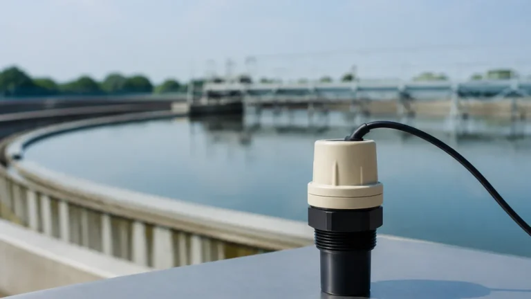
In industrial process control, monitoring the volume of liquids or solids within a vessel is fundamental to operational efficiency and safety. The use of an ultrasonic level sensor tank configuration has become a standard across industries such as water treatment, chemical processing, and industrial automation. These non-contact instruments offer a balance of accuracy, ease of installation, and cost-effectiveness that makes them a preferred choice for many engineers.
As a professional manufacturer of industrial level measurement instruments, Welk provides advanced solutions designed to meet the rigorous demands of global industrial environments. This guide examines the technical principles, selection criteria, and installation best practices for Ultrasonic Level Meters used in tank applications.
Measurement Principles of Ultrasonic Technology
Ultrasonic level measurement is based on the "Time of Flight" (ToF) principle. The sensor, typically mounted at the top of the tank, contains a piezoelectric transducer that emits high-frequency sound pulses. These sound waves travel through the air gap between the sensor and the material surface.
The Calculation Process
When the sound wave hits the surface of the liquid or solid, it reflects back toward the sensor. The instrument measures the time interval between the emission of the pulse and the reception of the echo. The distance ($D$) is calculated using the formula:
$$D = \frac{c \times t}{2}$$
Where:
* $c$: The speed of sound in the medium (typically air, approximately 344 m/s or 1,128 ft/s at 20°C).
* $t$: The total travel time for the pulse to go to the surface and return.
Since the height of the tank ($H$) is a known constant programmed into the device, the level ($L$) of the material is determined by subtracting the distance from the total height ($L = H – D$).
Temperature Compensation
The speed of sound is highly sensitive to temperature changes. For every degree Celsius change, the speed of sound varies by approximately 0.6 m/s. To maintain accuracy, modern ultrasonic level sensor tank units include integrated temperature sensors to automatically adjust the calculation based on ambient air temperature within the vessel.
Key Criteria for Tank Selection
Choosing the right ultrasonic level sensor for a tank requires an understanding of both the material being measured and the physical characteristics of the vessel. Not all ultrasonic meters are suitable for every environment.
1. Measurement Range and Beam Angle
The range of the sensor must exceed the maximum height of the tank. However, engineers must also consider the beam angle. A wider beam angle is more likely to hit internal obstructions like ladders, agitators, or weld seams, which can cause false echoes. For narrow or cluttered tanks, a sensor with a narrow beam angle (typically 5° to 10°) is required.
2. Material Compatibility
While the sensor is non-contact, the transducer face is exposed to the atmosphere inside the tank. For corrosive chemical tanks, the wetted parts—often the transducer face—should be constructed from chemically resistant materials like PVDF (Polyvinylidene fluoride) or PTFE (Teflon).
3. Integrated vs. Remote Electronics
* Integrated (Compact) Designs: The transducer and electronics are housed in a single unit. These are ideal for standard water tanks and simple industrial applications.
* Remote Designs: The transducer is mounted on the tank, while the display and control electronics are located in a separate enclosure, often at eye level or in a control room. This is preferred for hazardous environments or tanks where access is difficult.
Practical Selection Table for Ultrasonic Level Meters
| Feature | Standard Water/Waste | Chemical Storage | Industrial Silos (Solids) |
| :— | :— | :— | :— |
| Typical Range | 0.3m – 15m (1ft – 49ft) | 0.25m – 10m (0.8ft – 33ft) | 0.5m – 20m (1.6ft – 65ft) |
| Transducer Material | ABS / PVC | PVDF / PTFE | Reinforced Polymer |
| Protection Rating | IP66 / IP67 | IP68 / Explosion Proof | IP65 / Dust-Ignition Proof |
| Output Signal | 4-20mA / RS485 | 4-20mA / HART | 4-20mA / Modbus |
| Accuracy | ±0.25% to ±0.5% | ±0.2% | ±0.5% to ±1.0% |
Installation Considerations for Tank Mounting
Proper installation is the most critical factor in ensuring the reliability of an ultrasonic level sensor tank system. Even the most advanced sensor will fail if positioned incorrectly.
The Blocking Distance (Dead Zone)
Every ultrasonic sensor has a "dead zone" or blocking distance directly beneath the transducer face where it cannot measure. This is caused by the time required for the transducer to stop vibrating after emitting a pulse before it can listen for the return. If the liquid level enters this zone, the sensor will provide erratic readings. The sensor must be mounted high enough so that the maximum liquid level never reaches the blocking distance (typically 0.2m to 0.5m depending on the model).
Positioning and Alignment
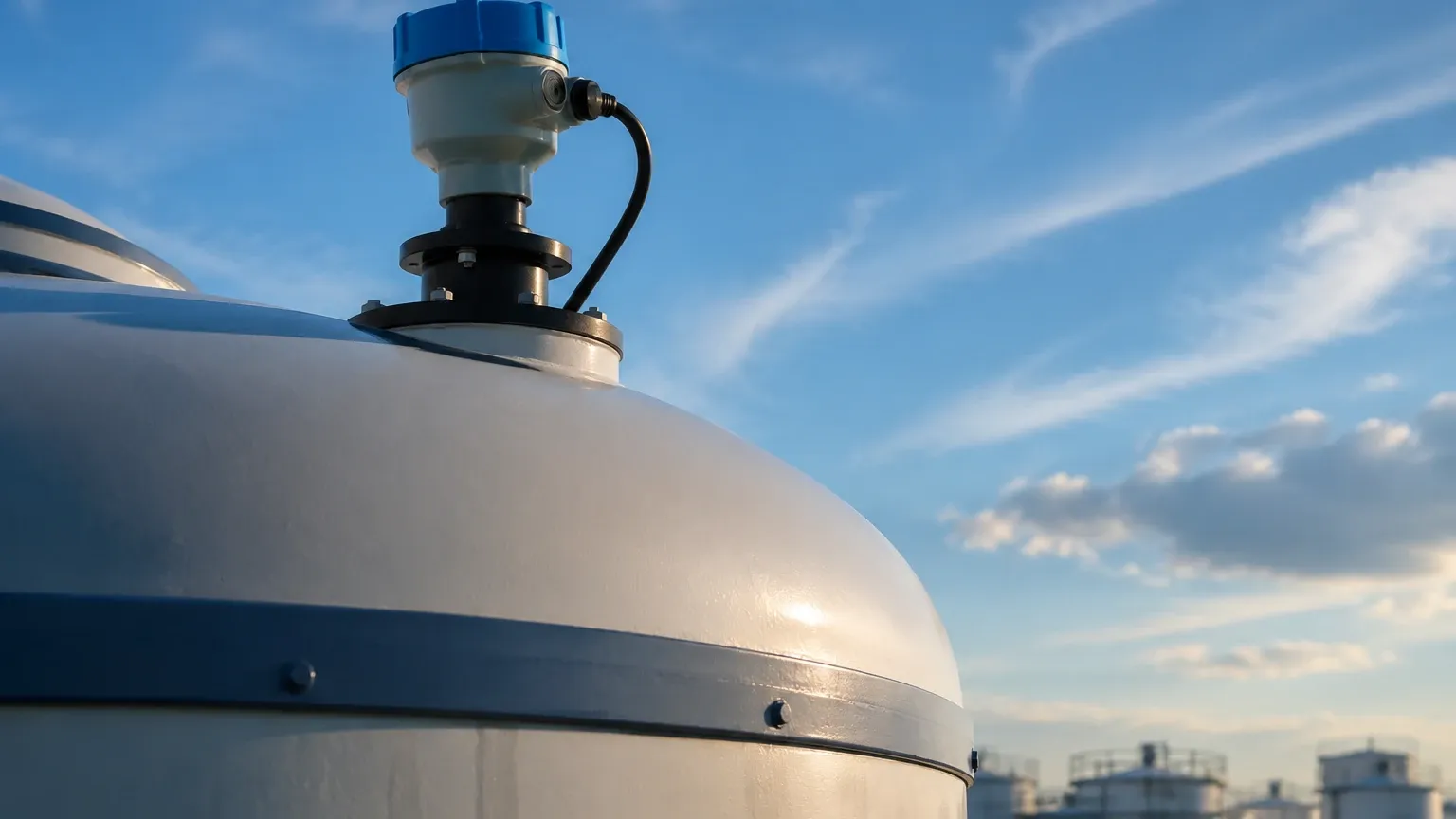
* Avoid the Center: In rounded or dome-top tanks, mounting the sensor in the exact center can create a "parabolic effect," where multiple reflections converge, leading to signal interference. It is generally recommended to mount the sensor at 1/2 to 2/3 of the radius from the center.
* Perpendicularity: The sensor must be mounted perfectly perpendicular to the liquid surface. A tilt of even a few degrees can cause the sound wave to reflect away from the transducer, resulting in a "loss of echo" error.
* Fill Stream Interference: Never mount the sensor directly above the tank's inlet. The falling stream of liquid will obstruct the ultrasonic pulse and cause false high-level readings.
Internal Obstructions
If the tank contains internal structures like heating coils, support struts, or ladders, the sensor should be positioned to avoid them. Many Welk Ultrasonic Level Meters feature "false echo suppression" software, allowing the user to program the device to ignore static reflections from fixed internal obstructions.
Limitations and Environmental Factors
While ultrasonic technology is versatile, certain process conditions can attenuate or distort the signal.
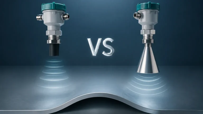
1. Heavy Foam: Surface foam acts as an acoustic absorber. Light, airy foam may allow some signal through, but thick, dense foam often absorbs the ultrasonic pulse entirely, making measurement impossible. In these cases, a radar level meter or hydrostatic transmitter may be more appropriate.
2. Vacuum and Pressure: Sound requires a medium (air or gas) to travel. Therefore, ultrasonic sensors cannot function in a vacuum. Furthermore, high-pressure environments change the density of the gas, which significantly alters the speed of sound and requires specialized calibration.
3. Vapor and Dust: Heavy steam or dense dust clouds can scatter the ultrasonic signal. While mild vapor is manageable, extreme conditions may require the higher frequency and penetration capabilities of radar technology.
4. Agitation: Rapidly moving or turbulent liquid surfaces can scatter the echo. While software filtering can smooth out these fluctuations, a stilling well (a vertical pipe installed in the tank) is often used to provide a calm surface for the sensor to measure.
Maintenance and Troubleshooting
Ultrasonic sensors are generally low-maintenance because they have no moving parts. However, periodic checks are recommended:
* Transducer Cleaning: In tanks with high humidity or splashing, condensation or material buildup can occur on the transducer face. This should be wiped clean with a soft cloth and mild detergent if accuracy begins to drift.
* Cable Integrity: Ensure that cable glands are tight and that there is no moisture ingress into the housing, which can cause short circuits or signal noise.
* Signal Strength Monitoring: Most digital ultrasonic meters provide a signal strength or "echo quality" metric. A sudden drop in signal strength often indicates that the transducer face is dirty or that the process environment (e.g., foam levels) has changed.
Frequently Asked Questions (FAQs)
Q: Can I use an ultrasonic sensor for solids like grain or plastic pellets?
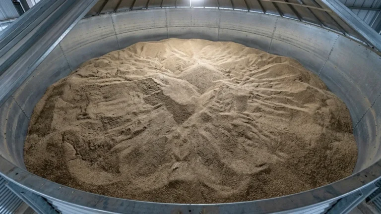
A: Yes, but with caveats. Solids do not reflect sound as uniformly as liquids. The surface is often angled (angle of repose), which can deflect the signal. You should choose a sensor specifically rated for solids, which usually has a higher power output and specialized signal processing.
Q: How do I handle a tank with a very narrow neck?
A: If the tank has a narrow mounting nozzle, ensure the nozzle is as short as possible. If the nozzle is too long or narrow, the ultrasonic pulse will reflect off the nozzle walls before even reaching the tank. This is known as "ringing."
Q: What is the maximum temperature an ultrasonic sensor can handle?
A: Most standard industrial ultrasonic sensors are rated for temperatures between -40°C and +70°C (-40°F to 158°F). For higher temperatures, the electronics may fail, and the speed of sound becomes more difficult to compensate for accurately.
Conclusion
Implementing an ultrasonic level sensor tank solution provides a reliable, non-intrusive method for monitoring industrial assets. By understanding the physics of sound travel and adhering to strict installation guidelines regarding blocking distances and obstructions, engineers can achieve highly accurate results. For applications involving extreme pressures, vacuums, or heavy foam, Welk offers a broader range of radar and hydrostatic level measurement technologies to ensure every process is covered with precision.