1 Ultrasonic
1 Ultrasonic
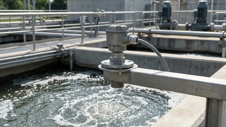
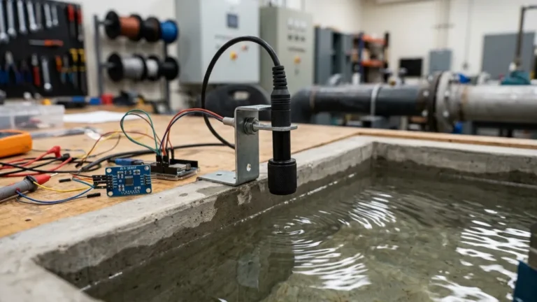
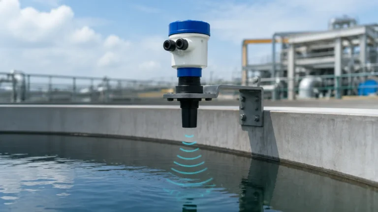
In the landscape of industrial automation, precise level measurement is a cornerstone of operational efficiency and safety. Among the various technologies available, Ultrasonic Level Meters have emerged as a primary choice for non-contact sensing. This guide explores the fundamental principles, selection criteria, and technical nuances of implementing a "1 ultrasonic" sensor system—referring to the standardized single-point measurement approach—within diverse industrial environments.
Understanding the Measurement Principle
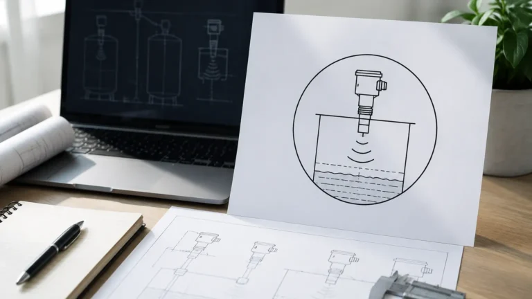
Before selecting a specific instrument, it is essential to understand the physics governing ultrasonic technology. An ultrasonic level meter operates on the Time-of-Flight (ToF) principle. The sensor, typically mounted at the top of a vessel, emits a high-frequency acoustic pulse. This pulse travels through the air space, reflects off the surface of the target medium (liquid or solid), and returns to the sensor.
The Time-of-Flight Equation
The distance from the sensor to the material surface is calculated using the following formula:
D = (c × t) / 2
Where:
* D is the distance to the surface.
* c is the speed of sound in the medium (usually air).
* t is the total time elapsed from emission to reception.
Since the speed of sound in air is approximately 344 m/s (1,128 ft/s) at 20°C (68°F), the instrument’s internal microprocessor converts this time interval into a precise distance. By subtracting this distance from the known total height of the tank, the device determines the actual level of the material.
Temperature Compensation
A critical factor in the "1 ultrasonic" measurement approach is temperature sensitivity. The speed of sound varies with air temperature (increasing by roughly 0.6 m/s per degree Celsius). Professional-grade Ultrasonic Level Meters from manufacturers like Welk include integrated temperature sensors to automatically compensate for these fluctuations, ensuring accuracy remains within ±0.25% to ±0.5% of the measured range.
Key Evaluation Criteria for Selection
Choosing the right ultrasonic instrument requires a thorough analysis of the application environment. Not all ultrasonic sensors are created equal; variations in frequency, power, and beam angle dictate their suitability for specific tasks.
1. Measurement Range and Dead Zone
Every ultrasonic sensor has a "dead zone" (also known as the blocking distance) directly beneath the transducer face. In this zone, the sensor cannot accurately process the returning signal because the transducer is still vibrating from the emission phase. Typical dead zones range from 0.2m to 0.5m (0.6ft to 1.6ft). Engineers must ensure the maximum liquid level never enters this zone to avoid erratic readings.
2. Beam Angle and Obstructions
The ultrasonic pulse spreads out in a cone shape. The beam angle (usually between 6° and 12°) determines the footprint of the signal at the target surface. If the beam hits internal tank structures like ladders, pipes, or agitators, it will trigger a "false echo." Selecting a sensor with a narrower beam angle is often necessary for narrow tanks or vessels with complex internal geometries.
3. Environmental Conditions
Ultrasonic waves are mechanical longitudinal waves. Their propagation is affected by the atmosphere through which they travel. Factors such as high pressure (which changes air density), vacuum (which prevents sound propagation), and heavy vapor or dust can attenuate the signal. For applications involving volatile chemicals or heavy steam, alternative technologies like radar may be considered, though modern ultrasonic filters can handle moderate vapor levels.
Technical Selection Table
The following table provides a reference for standard specifications found in industrial ultrasonic level measurement systems:
| Feature | Specification (Standard) | High-Performance Option |
| :— | :— | :— |
| Measurement Range | 0.3m – 10m (1ft – 33ft) | Up to 30m (98ft) |
| Accuracy | ±0.5% of Full Scale | ±0.2% of Full Scale |
| Output Signal | 4-20mA / HART | RS485 Modbus / GPRS |
| Power Supply | 24V DC (Two-wire) | 220V AC (Four-wire) |
| Operating Temp | -20°C to +60°C | -40°C to +95°C |
| Enclosure Rating | IP65 | IP68 (Submersible) |
| Beam Angle | 10° – 12° | 6° – 9° |
Installation Considerations and Best Practices
Proper installation is the most significant factor in the reliability of an ultrasonic level meter. Even the most advanced sensor will fail if positioned incorrectly.
Mounting Position
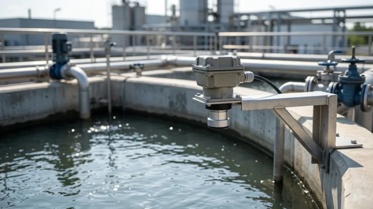
* Avoid the Center: In cylindrical tanks with domed tops, mounting the sensor in the exact center can cause multiple reflections to converge, resulting in signal interference. It is generally recommended to mount the sensor at 1/2 to 1/3 of the tank radius from the wall.
* Perpendicularity: The transducer face must be perfectly horizontal (perpendicular to the liquid surface). A tilt of even a few degrees can cause the reflected signal to miss the receiver, especially in long-range applications.
* Inflow Avoidance: Never install the sensor directly above the tank's fill inlet. The falling liquid or turbulence will disrupt the ultrasonic pulse and create significant noise.
Dealing with Turbulence and Foam
Surface turbulence can scatter the ultrasonic signal. While software algorithms can smooth out some fluctuations, severe turbulence may require the use of a stilling well—a vertical pipe that stabilizes the liquid surface for the sensor. Foam, however, is a more significant challenge; dense foam absorbs ultrasonic energy, often leading to a complete loss of signal. If foam is a persistent issue, contact Welk technical support for specialized transducer configurations.

Limitations of the "1 Ultrasonic" Approach
While highly versatile, ultrasonic technology has definitive boundaries:
1. Vacuum Applications: Sound cannot travel in a vacuum. Ultrasonic meters are unusable in vessels under full vacuum.
2. High Pressure: As pressure increases beyond 0.3 MPa (3 bar), the speed of sound changes significantly, and the transducer's diaphragm may be physically constrained.
3. Heavy Dust/Solid Build-up: In dry bulk solids measurement, heavy dust can attenuate the signal. Furthermore, if the material forms a steep cone (angle of repose), the signal may reflect away from the sensor rather than back toward it.
Maintenance and Troubleshooting
One of the primary benefits of Ultrasonic Level Meters is their low maintenance requirement, as they have no moving parts and do not contact the medium. However, periodic checks are recommended:
* Transducer Cleaning: In humid or dusty environments, condensation or material buildup can occur on the transducer face. Wiping the face with a soft cloth periodically ensures signal strength.
* Cable Integrity: Ensure that the shielded cable used for signal transmission is intact and away from high-voltage power lines to prevent electromagnetic interference.
* Diagnostic Echo Curves: Modern digital ultrasonic meters allow users to view an "echo curve" via software. This visual representation shows the strength of the return signal and helps identify the source of false echoes.
Frequently Asked Questions (FAQ)
Q: Can I use an ultrasonic level meter to measure the level of solids?
A: Yes, but with caveats. Solids like grain, coal, or plastic pellets have an angle of repose that can deflect the signal. You typically need a sensor with a higher power output and a swivelling mounting flange to aim the sensor correctly.
Q: How does wind affect outdoor installations?
A: Strong wind can "blow" the ultrasonic pulse away from its path, especially over long distances (e.g., in open channel flow measurement). Using a sunshade or wind shield can help maintain accuracy.
Q: What is the difference between a two-wire and a four-wire ultrasonic meter?
A: A two-wire system uses the same pair of wires for both power and the 4-20mA signal, which is ideal for standard loops. A four-wire system separates power and signal, allowing for higher power consumption (useful for long-range sensors or those with backlit displays and multiple relays).
Q: Is it possible to measure through a plastic tank wall?
A: No. While some specialized low-power sensors exist for very thin containers, industrial ultrasonic level meters require a clear path to the surface. The pulse will reflect off the tank top rather than passing through it.
Conclusion
The implementation of a "1 ultrasonic" measurement solution offers a cost-effective, reliable, and non-invasive way to monitor levels in water treatment, chemical storage, and industrial sumps. By respecting the physical limitations of acoustic waves and following rigorous installation standards, engineers can achieve high-precision results that enhance the automation of the entire process chain. For specific application engineering or customized OEM solutions, consulting with a specialized manufacturer like Welk ensures that the selected instrument is perfectly matched to the operational environment.