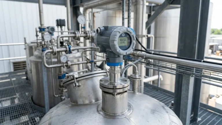
E H Ultrasonic Level Sensor
E H Ultrasonic Level Sensor: A Practical Engineering Guide to Selection and Application
In the realm of industrial process automation, non-contact level measurement has become the gold standard for reliability and low maintenance. Among the most recognized names in this field is the e h ultrasonic level sensor series, specifically the Prosonic line by Endress+Hauser. These instruments have set a high benchmark for accuracy and durability in water treatment, chemical processing, and solids handling. However, for procurement managers and process engineers, understanding the underlying technology and the competitive landscape of Ultrasonic Level Meters is essential for optimizing both performance and project budgets.
This guide explores the technical principles of ultrasonic measurement, evaluates the criteria that define high-performance sensors like the e h ultrasonic level sensor, and provides practical advice for selecting the right instrument for your specific application.
Understanding the Measurement Principle
Ultrasonic level measurement is based on the "Time-of-Flight" (ToF) principle. The sensor, typically mounted at the top of a tank or vessel, contains a piezoelectric transducer that emits a burst of mechanical sound waves (ultrasonic pulses) toward the surface of the medium.
The Physics of the Echo
1. Emission: The transducer converts electrical energy into an ultrasonic pulse.
2. Propagation: The pulse travels through the air (or gas) at the speed of sound.
3. Reflection: Upon hitting the surface of the liquid or solid, a portion of the energy is reflected back toward the sensor.
4. Reception: The transducer receives the returning echo and converts it back into an electrical signal.
The distance ($D$) from the sensor to the material surface is calculated using the formula:
$$D = \frac{c \times t}{2}$$
Where:
* $c$ is the speed of sound in the medium (approx. 344 m/s in air at 20°C).
* $t$ is the total elapsed time from emission to reception.
Since the total height of the tank ($H$) is known, the level ($L$) is determined by subtracting the measured distance from the tank height ($L = H – D$).
Temperature Compensation
The speed of sound is highly dependent on the temperature of the gas through which it travels. A change of 1°C can result in a 0.17% error in distance measurement. Professional-grade Ultrasonic Level Meters, including the e h ultrasonic level sensor series, incorporate integrated temperature sensors to automatically adjust the calculation, ensuring accuracy across varying environmental conditions.
Evaluating the e h ultrasonic level sensor and Market Alternatives
When engineers specify an e h ultrasonic level sensor, they are often looking for the reliability associated with the Prosonic FMU30, FMU40, or FMU90 series. These devices are known for their robust signal processing and ability to handle complex tank geometries. However, modern industrial automation has seen the rise of high-quality alternatives from manufacturers like Welk, which offer comparable performance with enhanced cost-efficiency.
Key Evaluation Criteria
When comparing ultrasonic sensors, consider the following technical specifications:
* Blocking Distance (Dead Zone): This is the area directly below the sensor where measurement is impossible. For short-range sensors, this might be as small as 0.25 meters, while long-range sensors for silos may have a blocking distance of 0.5 meters or more.
* Beam Angle: A narrower beam angle (typically between 5° and 11°) is preferable as it minimizes the risk of false echoes from tank internal structures like ladders, agitators, or weld seams.
* Frequency: High-frequency sensors (e.g., 70 kHz) are used for shorter ranges and provide higher resolution, while lower frequencies (e.g., 30 kHz) are used for longer ranges and are better at penetrating dust or steam.
* Signal Processing Algorithms: Advanced sensors use "echo mapping" to record and ignore static reflections from internal obstructions, focusing only on the true level signal.
Selection Guide for Ultrasonic Level Meters
Choosing the correct sensor requires a match between the instrument's capabilities and the application's physical constraints. The following table provides a general framework for selection:
| Application Type | Recommended Range | Key Feature Required | Typical Environment |
| :— | :— | :— | :— |
| Water Storage Tanks | 0.5m – 10m | IP68 Rating, Solar Power Compatibility | Ambient Outdoor |
| Chemical Dosing | 0.25m – 5m | PVDF or PTFE Wetted Parts | Corrosive Vapors |
| Open Channel Flow | 0.3m – 6m | Integrated Flow Formulas (Parshall Flumes) | Wastewater Plants |
| Solid Silos (Grains) | 1m – 20m | High Power Transducer, Dust Compensation | Dusty, Low Dielectric |
| Sumps & Pits | 0.5m – 8m | Submergence Protection, Narrow Beam | High Humidity |
For specialized chemical applications where an e h ultrasonic level sensor might be the traditional choice, ensure that any alternative Ultrasonic Level Meters offer equivalent material compatibility, such as PVDF transducers for acid resistance.
Installation Best Practices
Correct installation is the most critical factor in the success of an ultrasonic level system. Even the most advanced e h ultrasonic level sensor will fail if the physical mounting is flawed.
1. Positioning
* Avoid the Center: Do not mount the sensor in the exact center of a circular tank, as this can cause multiple reflections that amplify noise.
* Avoid the Wall: Keep the sensor at least 200mm to 500mm away from the tank wall to prevent the beam from hitting the side.
* Perpendicularity: The sensor face must be perfectly parallel to the liquid surface. A deviation of just a few degrees can cause the signal to bounce away from the receiver.
2. Nozzle Geometry
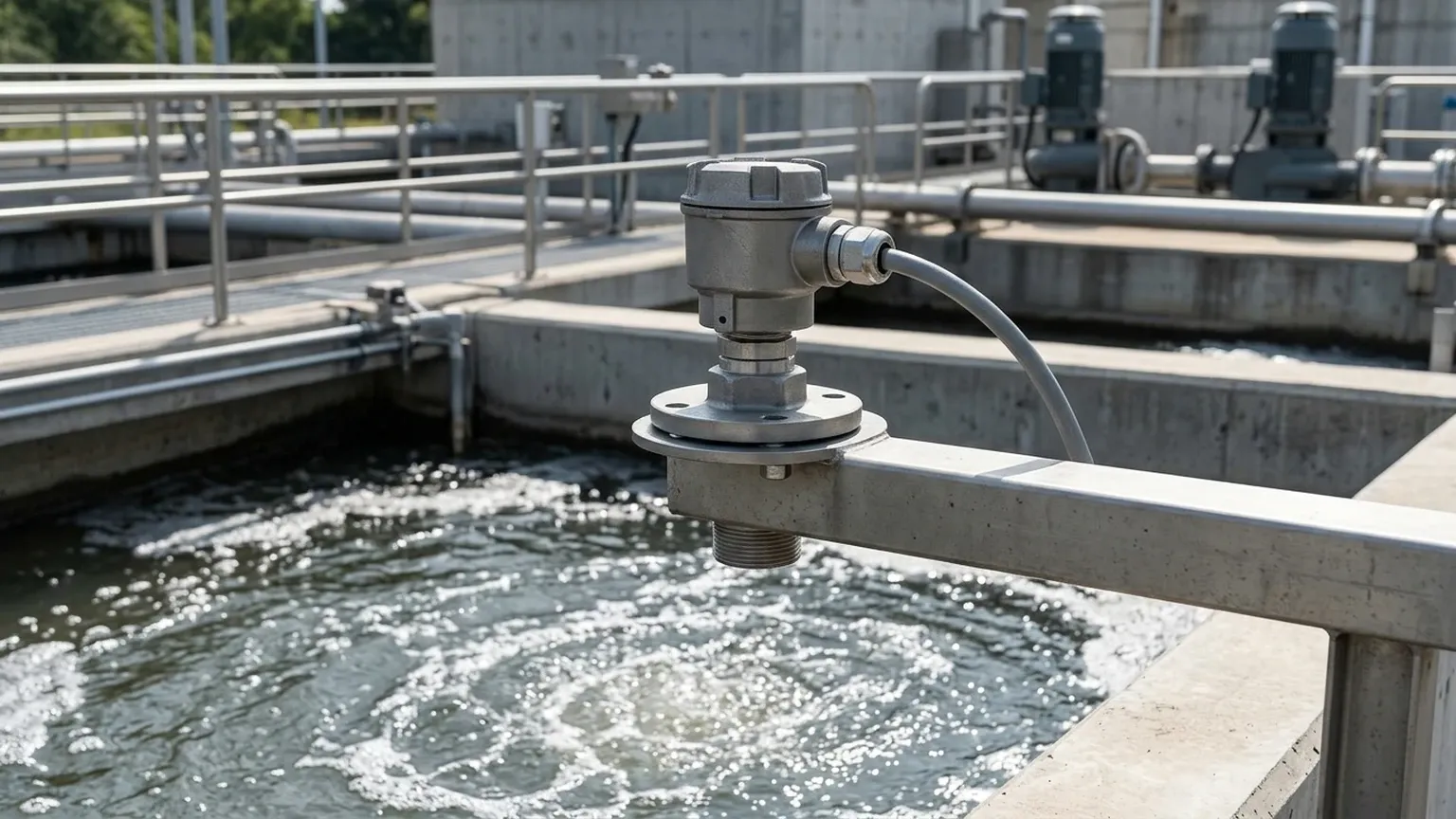
If mounting the sensor on a nozzle, ensure the nozzle is as short and wide as possible. If the nozzle is too narrow or too long, the ultrasonic pulse will reflect off the inside of the pipe before reaching the tank, creating a "false high" reading. The sensor face should ideally protrude slightly into the tank.
3. Avoiding Obstructions
Ensure the "signal cone" (defined by the beam angle) is clear of agitators, heating coils, and fill streams. If an obstruction is unavoidable, use a sensor with software-based false-echo suppression to "mask" the interference.
Limitations and When to Consider Alternatives
While Ultrasonic Level Meters are versatile, they are not universal solutions. Certain process conditions will interfere with the physics of sound:
* Heavy Foam: Foam absorbs ultrasonic pulses rather than reflecting them. If the foam is thick and dense, the sensor may report a "Loss of Echo" (LOE) error.
* Vacuum Conditions: Sound cannot travel through a vacuum. For vacuum tanks, a guided wave radar or hydrostatic pressure transmitter is required.
* High Temperature/Pressure: Standard ultrasonic sensors are typically limited to temperatures below 80°C and pressures below 3 bar. Beyond these limits, the transducer materials may degrade, and the speed of sound becomes too unpredictable.
* Vapor Layers: In tanks containing solvents or chemicals that create heavy vapor layers (like toluene), the speed of sound changes significantly, leading to large measurement errors unless the gas composition is constant and calibrated.
In these scenarios, transitioning from an e h ultrasonic level sensor to a radar-based system (80GHz) is often the recommended engineering path.
Maintenance and Troubleshooting
Ultrasonic sensors are generally low-maintenance because they have no moving parts and do not touch the medium. However, occasional checks are necessary:
* Condensation: In high-humidity applications, water droplets can form on the transducer face. Many modern sensors, including those from Welk and the e h ultrasonic level sensor range, feature a self-cleaning effect through the vibration of the transducer, but manual cleaning with a soft cloth may be needed in extreme cases.
* Build-up: In wastewater sumps, grease or fats can splash onto the sensor. Regular inspection ensures the signal remains strong.
* Diagnostics: Use the built-in diagnostic tools to monitor "Echo Strength" or "Signal-to-Noise Ratio" (SNR). A declining SNR is an early warning of environmental changes or sensor degradation.
Frequently Asked Questions (FAQ)
Q: Can an ultrasonic sensor measure the level of solids?
A: Yes, but the range is typically reduced by 50% compared to liquids because solids (like grain or plastic pellets) scatter the sound waves and have lower reflectivity. A high-power transducer is required.
Q: How does wind affect outdoor ultrasonic measurements?
A: Strong wind can "blow" the ultrasonic pulse away, preventing the echo from returning to the sensor. In outdoor open-channel flow applications, using a protective shield or a stilling well can mitigate this.
Q: What is the difference between a 2-wire and 4-wire ultrasonic meter?
A: A 2-wire device is loop-powered (the same two wires carry the 4-20mA signal and provide power), which is easier to install. A 4-wire device has separate power and signal wires, allowing for higher-power pulses and more intensive signal processing, which is useful for long-range or difficult applications.
Q: Is it possible to use an e h ultrasonic level sensor in a pressurized tank?
A: Most ultrasonic sensors are designed for atmospheric pressure. While some can handle up to 3 bar (approx. 43 psi), higher pressures significantly change the density of the air, requiring specialized calibration or a different technology like radar.
For engineers seeking reliable, cost-effective alternatives to the e h ultrasonic level sensor, exploring the full range of Ultrasonic Level Meters provides the flexibility to meet specific process requirements without compromising on accuracy or industrial-grade durability.