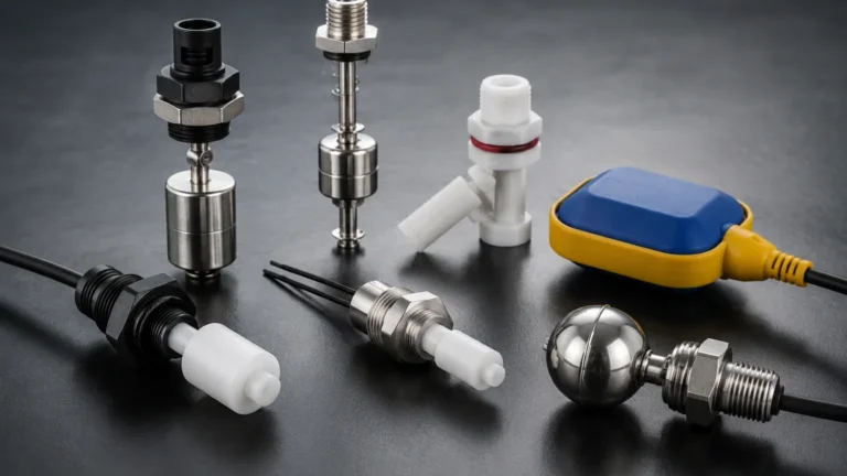
Conductivity Level Switches
Conductivity Level Switches
In the field of industrial process control, point level detection serves as a critical safeguard for preventing tank overfills, protecting pumps from dry running, and managing automated filling sequences. Among the various technologies available, conductivity level switches represent one of the most robust and cost-effective solutions for detecting the presence or absence of conductive liquids. These devices are widely utilized in water treatment, chemical processing, and the food and beverage industry due to their lack of moving parts and high reliability.
As part of a comprehensive instrumentation strategy, Level Switches are selected based on the physical and chemical properties of the process media. For applications involving water-based liquids or acids, conductivity level switches offer a specialized approach that leverages the electrical properties of the fluid itself.
Measurement Principles
Conductivity level switches operate on the principle of electrical resistance. The system typically consists of an electrode (the probe) and a reference point, which can be either a second electrode or the conductive wall of a metal tank.
When the liquid level rises and makes contact with the electrode, an electrical circuit is completed between the probe and the reference. The liquid acts as a conductor, allowing a small amount of current to flow. This change in resistance is detected by a control unit (an evaluation relay), which then triggers a switching output, such as a relay contact or a transistor signal. Conversely, when the liquid level falls below the electrode, the circuit is broken, and the switch returns to its original state.
AC vs. DC Excitation
To prevent the effects of electrolysis and polarization—which can lead to the buildup of ions on the probe and eventual corrosion or measurement drift—most modern conductivity level switches use a low-voltage Alternating Current (AC). The frequency of this AC signal is specifically designed to ensure long-term electrode stability and accurate detection even in liquids with varying ion concentrations.
Sensitivity and Conductivity Thresholds
The effectiveness of these switches depends on the conductivity of the medium, measured in Microsiemens per centimeter (μS/cm). While many industrial liquids are highly conductive (such as wastewater or acids), others like purified water have very low conductivity. Most controllers feature adjustable sensitivity settings, allowing the switch to be tuned to the specific resistance of the process fluid, typically ranging from 1 μS/cm to 50,000 μS/cm.
System Components and Design
A complete conductivity level detection system generally comprises three main elements: the electrodes, the process connection, and the electronic evaluation unit.
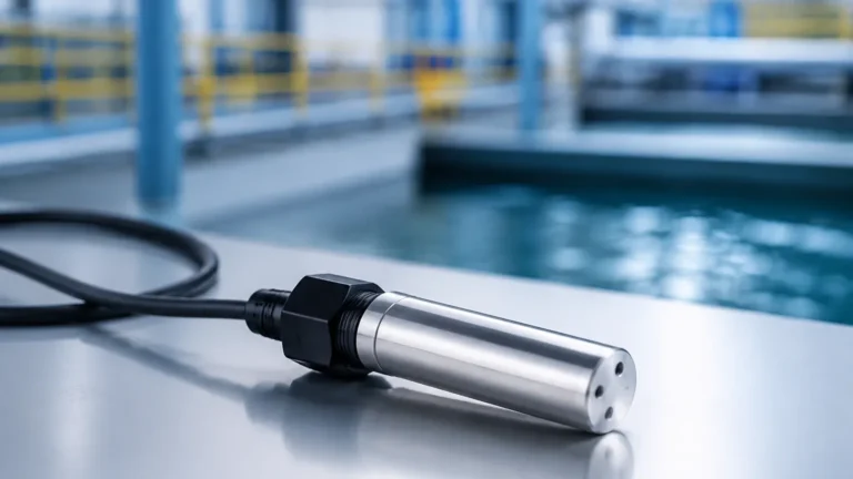
1. Electrodes (Probes): These are the sensing elements that enter the tank. They can be rigid rods for shorter distances (typically up to 3 meters) or flexible cables for deep sumps or large reservoirs (up to 15 meters or more). Materials are chosen based on chemical compatibility, with 316L stainless steel being the standard, while Hastelloy or titanium are used for highly aggressive media.
2. Insulation: The electrodes must be insulated from the tank wall and from each other (in multi-probe units) to prevent short circuits. Common insulation materials include PTFE (Polytetrafluoroethylene), PEEK, or Polypropylene.
3. Evaluation Unit: This is the "brain" of the switch. It can be integrated into the sensor head (compact design) or mounted remotely in a control cabinet. The unit manages the power supply to the probes and processes the switching logic.
Types of Conductivity Level Switches
Depending on the complexity of the process, engineers can choose between single-point and multi-point configurations.
Single-Point Switches
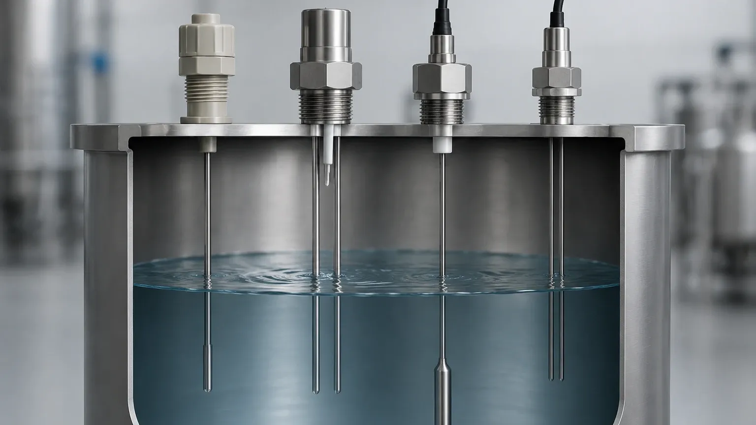
These are used for basic high-level or low-level alarms. A single probe is installed at the desired trigger point. In a metal tank, the tank wall serves as the ground return. In a plastic tank, a second "earth" probe must be installed alongside the sensing probe to complete the circuit.
Multi-Point Switches
Multi-point conductivity level switches allow for the monitoring of several levels within a single process connection. A single probe head can support up to five or more rods of different lengths. This is ideal for controlling a pump (start at one level, stop at another) while also providing independent high-high and low-low safety alarms. This consolidated design reduces the number of tank penetrations required, lowering the risk of leaks and reducing installation costs.
Practical Selection Table
When choosing between different point level technologies, it is helpful to compare conductivity level switches against other common alternatives.
| Feature | Conductivity Switch | Float Switch | Ultrasonic Point Switch |
| :— | :— | :— | :— |
| Media Type | Conductive liquids only | Most liquids | Most liquids/solids |
| Moving Parts | None | Yes (Mechanical) | None |
| Maintenance | Very Low | Moderate (Fouling risk) | Low |
| Cost | Low to Moderate | Low | Moderate to High |
| Viscosity Limit | Low to Medium | Low to Medium | High |
| Conductivity Req. | Yes (Typically >5 μS/cm) | No | No |
| Pressure Range | Up to 100 bar | Up to 40 bar | Up to 20 bar |
Installation Considerations
Proper installation is paramount to ensuring the longevity and accuracy of conductivity level switches. Engineers should adhere to the following guidelines:
* Mounting Orientation: While vertical mounting from the top of the tank is most common (especially for rod probes), some compact conductivity switches can be mounted horizontally. If mounted horizontally, the probe should be angled slightly downward to ensure liquid drains off the tip, preventing "bridging" or false triggers.
* Distance from Walls: Probes should be installed at least 50 mm away from the tank wall or other internal structures to avoid capacitive interference or accidental grounding.
* Reference Electrode: In non-conductive tanks (plastic, fiberglass, or lined steel), always include a reference electrode that is longer than the longest switching electrode to ensure a continuous return path for the electrical circuit.
* Turbulence and Foam: If the liquid surface is highly turbulent, a stilling well may be required to prevent rapid cycling of the relay. While conductivity switches are generally resistant to light foam, dense conductive foam may trigger the switch prematurely. Adjusting the sensitivity on the controller can often mitigate this issue.
Limitations and Risks
While highly effective, conductivity level switches are not universal solutions. Understanding their limitations prevents application failure.
1. Non-Conductive Media: These switches cannot detect oils, hydrocarbons, pure alcohols, or demineralized water with extremely low ion content (typically <1 μS/cm).
2. Coating and Buildup: If the process liquid is highly viscous or prone to crystallization, a film may form across the insulation between the probe and the ground. This "bridging" can create a permanent conductive path, causing the switch to remain in the "on" state even after the liquid level has dropped. In such cases, a vibration-style level switch or a capacitive switch with coating rejection might be more appropriate.
3. Electrode Corrosion: Although AC current minimizes corrosion, the electrodes must still be chemically compatible with the media. Regular inspection is recommended in highly corrosive chemical applications to ensure the structural integrity of the probes.
Industry Applications
Conductivity level switches are found in nearly every sector where water-based processes are managed:
* Water and Wastewater: Monitoring levels in sumps, sewage lift stations, and reagent tanks for water treatment chemicals.
* Food and Beverage: Detecting levels in milk tanks, juice processing, and Clean-in-Place (CIP) systems where conductivity changes can also help distinguish between product and cleaning solution.
* Power Generation: Controlling water levels in steam boilers (low-water cut-off) and condensate return tanks.
* Industrial Automation: General header tank control and cooling tower basin management.
Frequently Asked Questions (FAQs)
Q: Can conductivity level switches be used in flammable environments?
A: Yes, but they must be used in conjunction with an intrinsically safe barrier or an explosion-proof housing, depending on the hazardous zone classification (ATEX/IECEx).
Q: How do I test a conductivity switch during commissioning?
A: The simplest method is to use a wire to momentarily bridge the sensing electrode to the ground (tank wall or reference probe). If the controller is functioning, the output relay should click or the LED indicator should change state.
Q: What is the maximum temperature these switches can handle?
A: This depends on the insulation material. PTFE-insulated probes can typically handle up to 200°C (392°F), though the electronics in compact models may have lower limits (usually around 80°C to 100°C).
Q: Do the probes need to be cleaned?
A: In clean water applications, they are virtually maintenance-free. In wastewater or chemical applications, periodic cleaning may be necessary to remove scale or biological growth that could cause false readings.
Conclusion
Conductivity level switches remain a staple of industrial instrumentation because they provide a simple, effective, and durable method for point level control. By understanding the conductivity of the media and selecting the appropriate probe materials and controller sensitivity, engineers can implement a level detection system that requires minimal maintenance over a long service life. For more complex requirements involving non-conductive fluids or continuous level monitoring, other technologies within the broader range of industrial level measurement may be required, but for conductive liquids, the conductivity switch is often the most efficient choice available.