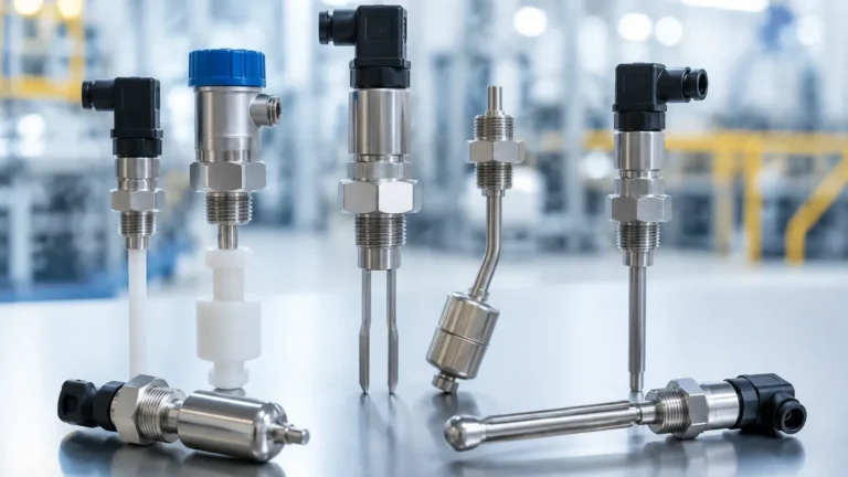
Switches G
Switches G
In the landscape of industrial automation and process control, level switches serve as the fundamental sentinels of safety and efficiency. Among the various specifications encountered by engineers, the term "switches G" frequently refers to level switches equipped with G-series threaded connections—a standard derived from the British Standard Pipe Parallel (BSPP) system. These components are essential for point-level detection in tanks, silos, and pipelines, ensuring that processes remain within defined volumetric boundaries.
Selecting the correct level switch requires a deep understanding of both the measurement physics and the mechanical interface. Whether managing aggressive chemicals or potable water, the integration of Level Switches into a system depends on matching the sensing technology to the physical properties of the medium and the mechanical requirements of the vessel.
Measurement Principles of Level Switches
Before selecting a specific model of switches G, it is vital to understand the underlying physical principles that govern point-level detection. Different technologies are suited for different media types, ranging from low-viscosity liquids to granular solids.
Vibrating Tuning Fork Principle
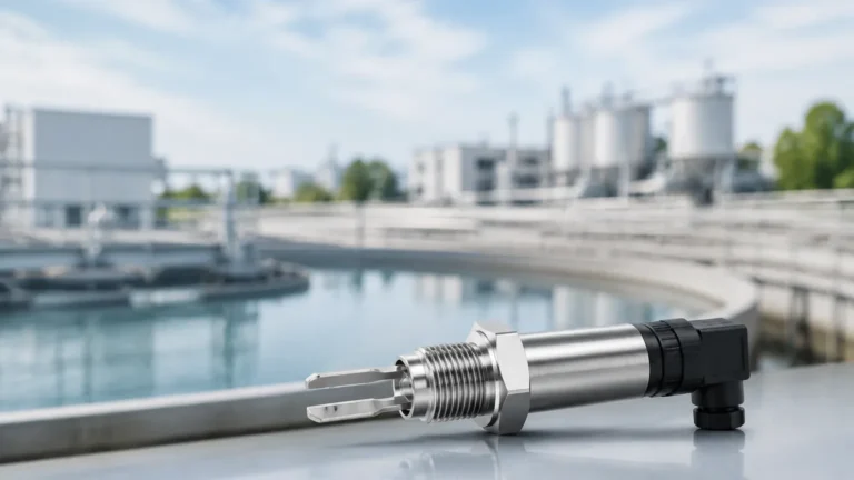
The vibrating level switch, often referred to as a tuning fork sensor, utilizes piezoelectric crystals to vibrate a metal fork at its natural resonant frequency in the air. When the fork is submerged in a liquid or covered by solids, the frequency changes or the vibration is damped. This shift is detected by the internal electronics, which then trigger a relay or transistor output. This technology is highly reliable because it is largely unaffected by flow, turbulence, bubbles, or foam.
Float and Magnetic Principle
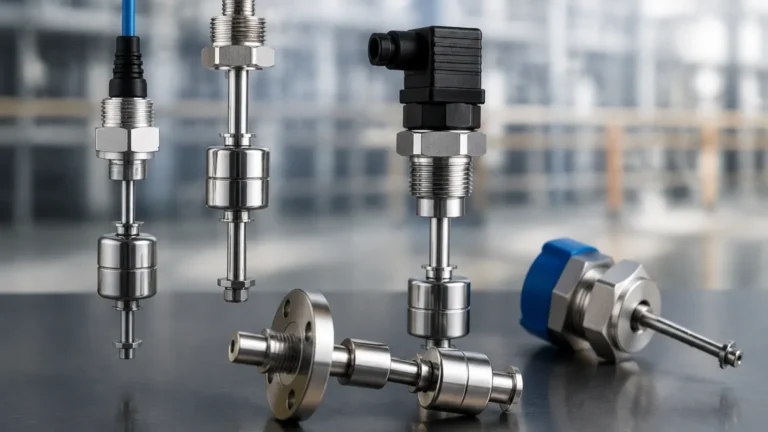
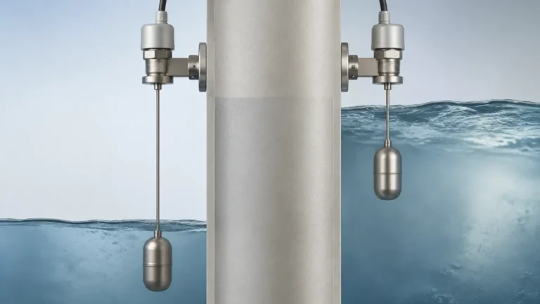
Float switches operate on the simple principle of buoyancy. A float containing a permanent magnet moves up and down a stem as the liquid level changes. Inside the stem, a hermetically sealed reed switch is actuated by the magnetic field. This is a passive technology that requires no external power to operate the sensing element itself, making it a cost-effective choice for simple water and oil applications.
Capacitive Level Detection
Capacitance switches treat the sensor probe and the tank wall (or a reference electrode) as two plates of a capacitor. The medium acts as the dielectric material. As the level rises and covers the probe, the capacitance increases due to the higher dielectric constant of the medium compared to air. This change is converted into a switching signal. Capacitive sensors are excellent for detecting powders, granulates, and liquids, though they may require calibration for specific materials.
Ultrasonic Point Level
Ultrasonic switches use a pair of crystals: one to transmit a high-frequency pulse and one to receive it across a small gap in the sensor head. When the gap is filled with air, the signal is weak; when filled with liquid, the signal transmits efficiently. This "gap technology" is ideal for non-contact-sensitive applications where the physical properties of the liquid might fluctuate.
The Significance of G-Thread Connections
The "G" in switches G refers to the ISO 228-1 standard for pipe threads where pressure-tight joints are not made on the threads. Unlike NPT (National Pipe Taper) threads, which seal by interference between the male and female threads, G-threads are parallel.
In industrial level measurement, G-threads (such as G1/2", G1", or G1 1/2") are preferred in many European and international markets because they allow for consistent orientation of the sensor. Since the threads do not taper, the sensor can be screwed in completely, and the seal is achieved via a flat gasket or an O-ring compressed between the sensor's hexagonal shoulder and the process connection face. This is particularly important for tuning fork switches, where the orientation of the forks must be specific to allow the medium to drain freely.
Selection Criteria for Switches G
Choosing the right level switch involves more than just selecting a thread size. Engineers must evaluate the process environment against the following criteria:
1. Media Density: Tuning forks require a minimum density (often measured in g/cm³) to function correctly. If the medium is too light, the frequency shift may be insufficient to trigger the switch.
2. Viscosity: High-viscosity liquids can cause "bridging" on tuning forks or stickiness on floats, leading to false readings.
3. Pressure and Temperature: Standard G-thread switches are often rated for pressures up to 40 bar and temperatures ranging from -40°C to +150°C. Specialized high-temperature versions are required for steam or molten applications.
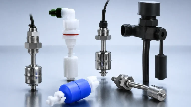
4. Chemical Compatibility: The wetted parts—usually Stainless Steel 316L, PP, or PTFE—must be resistant to the process fluid to prevent corrosion and premature failure.
Practical Selection Table
| Technology | Best For | Max Pressure (Typical) | Max Temp (Typical) | Viscosity Limit |
| :— | :— | :— | :— | :— |
| Vibrating Fork | Liquids, light solids | 40 bar | 150°C | Up to 10,000 mm²/s |
| Float Switch | Clean liquids, oils | 20 bar | 100°C | Low to Medium |
| Capacitance | Powders, granulates | 25 bar | 200°C | N/A (Solid dependent) |
| Conductive | Conductive liquids | 10 bar | 100°C | Low |
Installation Considerations for G-Threaded Switches
Proper installation is paramount to ensure the longevity and accuracy of the level switch. When installing switches G, follow these engineering guidelines:
* Sealing: Always use a compatible gasket (such as copper, PTFE, or NBR). Because G-threads are parallel, using thread-sealant tape (PTFE tape) is generally discouraged as it does not provide the primary seal and can interfere with the mechanical seating of the sensor.
* Positioning: For tuning fork switches, ensure the forks are oriented so that the liquid can easily flow out from between the tines. Most sensors have a marking on the hex nut to indicate the fork orientation.
* Avoid Turbulence: Do not install the switch directly in the path of a fill pipe. The force of the incoming material can cause mechanical damage or constant false switching.
* Nozzle Length: Ensure the sensing element (the forks or the float) extends sufficiently into the vessel. If the nozzle is too long, material may build up inside the nozzle and prevent the sensor from detecting the actual level in the tank.

Limitations and Common Risks
While level switches are robust, they are not universal solutions. Engineers should be aware of the following limitations:
* Build-up and Coating: In applications involving sticky resins or wastewater, material can build up on the sensor. While some capacitive and vibrating switches have "coat-rejection" logic, excessive build-up will eventually lead to a permanent "covered" signal.
* Turbulence and Agitation: In tanks with high-speed agitators, mechanical switches like floats can be physically damaged. In these cases, non-contact or shielded vibrating forks are preferred.
* Electromagnetic Interference (EMI): Electronic switches (capacitive/ultrasonic) must be properly grounded, especially in plastic tanks, to avoid false triggers from nearby heavy machinery or variable frequency drives (VFDs).
Maintenance and Calibration
Most modern level switches are designed to be maintenance-free. However, a periodic visual inspection is recommended, especially in corrosive environments. For capacitive switches, recalibration may be necessary if the moisture content or composition of the measured material changes significantly.
For vibrating forks, a "proof test" should be conducted annually. This involves manually raising the liquid level or removing the sensor to ensure the electronics correctly report the change in state. Many advanced switches G now feature self-monitoring electronics that can signal a fault if the piezoelectric crystal fails or if significant corrosion is detected on the forks.
Frequently Asked Questions (FAQs)
Q: Can I use a G-thread switch in an NPT port?
A: No. While they may seem similar in diameter, the thread pitch and angle (55° for G vs. 60° for NPT) are different. Forcing a G-thread into an NPT port will damage the threads and will not create a pressure-tight seal.
Q: What is the advantage of a G-thread over a flange connection?
A: Threaded connections are more compact and cost-effective for smaller vessels and pipes. Flanges are typically reserved for larger sensors or high-pressure/high-safety applications where a more robust mechanical seal is required.
Q: How do I choose between a PNP and NPN output for my level switch?
A: This depends on your PLC (Programmable Logic Controller). PNP (Sourcing) is standard in Europe and North America, where the switch provides a positive voltage when activated. NPN (Sinking) is more common in some Asian markets, where the switch connects the load to the ground.
Q: Is a G1/2" connection large enough for solids?
A: Generally, no. For powders and granulates, a larger connection like G1" or G1 1/2" is recommended to prevent the material from bridging across the opening and to allow for a more robust sensing element.
By carefully considering the measurement principle, the mechanical interface of the G-thread, and the specific demands of the process media, engineers can ensure that their level measurement system provides reliable, long-term performance in any industrial environment.