Level Switch Honeywell
Level Switch Honeywell
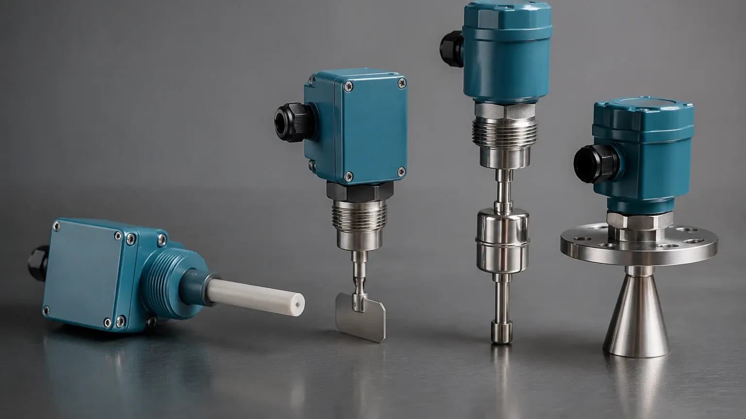
In the landscape of industrial automation and process control, point level detection remains a fundamental requirement for safety, efficiency, and inventory management. Among the various solutions available to engineers, the level switch Honeywell series and similar high-precision industrial sensors represent a critical category of components designed to detect the presence or absence of liquids or solids at specific heights within a vessel. This guide provides a technical overview of level switch technologies, focusing on the principles of operation, selection criteria for Honeywell-compatible systems, and practical installation considerations for industrial environments.
Understanding Level Switch Measurement Principles
Before selecting a specific model, such as a level switch Honeywell optical sensor or a vibrating fork alternative, it is essential to understand the physical principles that govern these devices. Level switches are "point level" devices, meaning they provide a discrete output (on/off) rather than a continuous measurement of the fluid level.
1. Optical Level Sensing
Honeywell is particularly well-known for its miniature optical liquid level sensors. These devices operate on the principle of total internal reflection. An LED and a phototransistor are housed within a plastic or glass dome at the sensing tip. When no liquid is present, the infrared light from the LED is reflected within the dome back to the sensor. When liquid covers the dome, the refractive index changes, causing the light to escape into the fluid, which triggers the switch output. This technology is highly reliable for clean liquids and requires no moving parts.
2. Vibrating Tuning Fork Principle
Widely used in more demanding industrial applications, vibrating level switches utilize a tuning fork driven by piezoelectric crystals. The fork vibrates at its natural resonant frequency in the air. When the fork is submerged in a liquid or covered by a solid, the frequency shifts or the amplitude is dampened. This change is detected by the electronics and converted into a switching signal. These are robust against turbulence, bubbles, and foam.
3. Float and Magnetic Principles
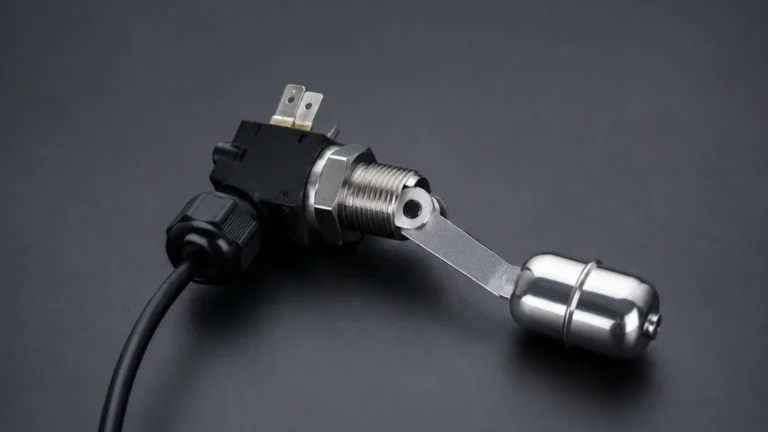
Mechanical level switches use a float containing a magnet that moves with the liquid level. As the float reaches a predetermined point, the magnetic field actuates a reed switch or a microswitch. While Honeywell produces a wide range of limit switches often used in mechanical linkages for level detection, pure magnetic float switches are more common in heavy industrial tank applications where power consumption must be minimized.
4. Capacitance Level Sensing
Capacitance switches measure the change in electrical capacitance between the sensor probe and the tank wall (or a reference probe). As the medium displaces air, the dielectric constant changes, altering the capacitance. This method is effective for both liquids and solids but requires calibration based on the specific material's dielectric properties.
Key Series in the Honeywell Level Switch Portfolio
Honeywell’s sensing and productivity solutions include several series that are frequently specified in B2B procurement for medical, HVAC, and industrial OEM applications.
* LLE Series: These are small-scale optical Level Switches designed for high-volume OEM use. They are often found in home appliances, medical equipment, and small industrial tanks. They offer fast response times and are generally compatible with a variety of aqueous and organic fluids.
* LLN Series: A more ruggedized version of the optical sensor, often housed in stainless steel or high-performance plastics to withstand harsher industrial chemicals and higher pressures (up to 25 bar or approximately 362 psi).
* LS and Limit Switch Series: While not always direct immersion sensors, Honeywell’s heavy-duty limit switches are frequently used in secondary level detection roles, such as monitoring the position of a weighted cable or a mechanical arm in a dry bulk silo.
Technical Selection Criteria for Industrial Level Switches
When evaluating a level switch Honeywell model or a Welk industrial alternative, engineers must match the sensor specifications to the process conditions. Failure to do so can lead to premature sensor failure or false triggering.
Media Characteristics
* Viscosity: High-viscosity liquids can coat optical prisms or clog tuning forks. For thick oils or resins, a high-torque rotary switch or a heavy-duty vibrating fork is preferred.
* Dielectric Constant: If using capacitance-based switches, the dielectric constant of the fluid must be significantly different from air.
* Corrosivity: Ensure the wetted materials (e.g., Polysulfone, Stainless Steel 316L, or Hastelloy) are compatible with the chemical makeup of the fluid.
Environmental Conditions
* Pressure: Standard optical switches may only handle up to 5-10 bar. For high-pressure boilers or chemical reactors, hydrostatic or specialized radar-based switches are necessary.
* Temperature: Honeywell’s standard LLE series typically operates up to 85°C. For steam applications or cryogenic storage, specialized high-temperature probes are required.
Electrical Requirements
* Output Type: Choose between NPN/PNP (for PLC integration), SPDT relay (for direct load switching), or 2-wire loops.
* Supply Voltage: Most industrial sensors operate on 12-24V DC, though some limit switches can handle 110/220V AC.
Practical Selection Table
The following table compares common level switch technologies used in industrial automation to help narrow down the choice between optical, vibrating, and mechanical types.
| Feature | Optical (e.g., Honeywell LLE) | Vibrating Fork | Magnetic Float | Capacitance |
| :— | :— | :— | :— | :— |
| Best For | Clean liquids, small spaces | Slurries, turbulent liquids | Simple water tanks | Powders and granules |
| Moving Parts | None | None | Yes (Float) | None |
| Maintenance | Low (keep prism clean) | Low | Moderate (cleaning float) | Low (calibration needed) |
| Pressure Limit | Up to 25 bar | Up to 64 bar+ | Up to 40 bar | Up to 100 bar |
| Temperature Range | -25°C to +125°C | -50°C to +150°C | -40°C to +200°C | -40°C to +250°C |
| Foam Sensitivity | High (can false trigger) | Low | None | Moderate |
Installation Considerations and Best Practices
Proper installation is as critical as selecting the right sensor. Even a high-quality level switch Honeywell component will fail if placed in an area of extreme turbulence or improper orientation.
1. Orientation: Most optical sensors can be mounted horizontally or vertically. However, if mounted horizontally, the prism should be angled slightly to allow liquid to drain off, preventing "clingage" from causing a false positive.
2. Avoid Turbulence: Do not install switches directly under a fill pipe. The splashing liquid will cause the switch to chatter. If unavoidable, use a stilling well or a protective baffle.
3. Wiring and Interference: For electronic switches, ensure that signal cables are shielded and kept away from high-voltage motor lines to prevent electromagnetic interference (EMI).
4. Sealing: Use appropriate thread sealant (PTFE tape or specialized pipe dope) and ensure the IP rating (e.g., IP67 or IP68) matches the washdown requirements of the facility.
Limitations and Common Risks
While Honeywell products are engineered for reliability, there are inherent limitations to point level detection that engineers must acknowledge:
* Coating and Buildup: In applications involving wastewater or crystalline solutions, material can build up on the sensor face. For optical sensors, this blocks the light path; for tuning forks, it changes the mass and frequency. Regular cleaning cycles or the use of "active shield" capacitance probes may be necessary.
* Ambient Light Interference: For unshielded optical switches, extremely bright sunlight or high-intensity strobe lights can occasionally interfere with the phototransistor. Most modern Honeywell sensors include infra-red filtering to mitigate this.
* Mechanical Wear: In float-based systems, pivot points can corrode or become stuck due to sediment. In high-vibration environments, mechanical microswitches may have a shorter lifespan than solid-state electronics.
Frequently Asked Questions (FAQ)
Q: Can a Honeywell optical level switch be used in oils?
A: Yes, provided the housing material (such as Polysulfone or Trogamid) is chemically compatible with the specific oil. Optical sensors are excellent for detecting oil levels because they are not dependent on the liquid's conductivity.
Q: How do I test if my level switch is functioning correctly?
A: For most electronic switches, a "dry" test can be performed by manually obstructing the sensor (for optical) or touching the fork (for vibrating). For float switches, manually moving the float while checking continuity with a multimeter is the standard procedure.
Q: What is the difference between N.O. and N.C. in level switches?
A: N.O. (Normally Open) means the circuit is open when the switch is "inactive" (usually dry). N.C. (Normally Closed) means the circuit is closed when inactive. Selecting the right state is crucial for fail-safe operations (e.g., using N.C. for high-level alarms so that a wire break also triggers the alarm).
Q: Are there Honeywell level switches rated for explosive atmospheres?
A: Honeywell produces several limit switches and specialized sensors with ATEX or UL hazardous area certifications. Always verify the specific "Ex" rating on the product datasheet before installing in a zone-rated area.
Conclusion
Selecting a level switch Honeywell solution requires a balance between technical specifications and the specific demands of the process media. Whether utilizing the precision of optical sensing for medical devices or the ruggedness of a limit switch for industrial positioning, understanding the underlying measurement principles is the first step toward a reliable installation. For broader industrial applications involving tanks, silos, and chemical processing, exploring a comprehensive range of Level Switches ensures that the chosen technology aligns with long-term operational goals and safety standards. By following established installation guidelines and considering the limitations of each technology, engineers can significantly reduce downtime and maintenance costs in their level control systems.