Level Switch Magnetic
Level Switch Magnetic
In the landscape of industrial process control, point-level detection is a critical requirement for safety, inventory management, and automated pump control. Among the various technologies available, the level switch magnetic design remains one of the most reliable and widely adopted solutions. Utilizing the fundamental principles of magnetism to actuate electrical contacts, these devices offer a hermetically sealed interface between the process fluid and the electrical system, ensuring longevity even in aggressive or high-pressure environments.
This guide explores the technical foundations of magnetic level switches, their selection criteria, and the practical considerations necessary for successful integration into industrial workflows. For engineers and procurement specialists, understanding these nuances is essential for maintaining operational efficiency and preventing costly overflows or dry-run conditions.
Fundamental Principles of Magnetic Level Measurement
The operation of a magnetic level switch is based on the interaction between two primary components: a permanent magnet and a reed switch. The reed switch consists of two overlapping, ferromagnetic blades (reeds) sealed within a glass envelope filled with an inert gas.
The Reed Switch Mechanism
When a magnetic field is brought into proximity with the reed switch, the two blades become magnetized with opposite polarities. The resulting attraction pulls the blades together, closing the electrical circuit. Conversely, when the magnetic field is removed, the inherent spring tension of the blades causes them to separate, opening the circuit. Because these contacts are sealed in glass, they are protected from oxidation, corrosion, and sparking, making them suitable for hazardous areas.
Float Dynamics
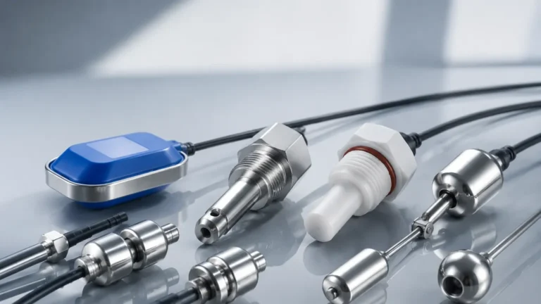
In a typical level switch magnetic configuration, the permanent magnet is encapsulated within a buoyant float. As the liquid level rises or falls, the float moves along a stem or pivots on a hinge. When the float reaches a predetermined position, the internal magnet aligns with the reed switch located inside the stationary stem or housing, triggering the state change. This mechanical-to-electrical conversion requires no external power to operate the sensing element itself, contributing to the device's high reliability.
Key Components and Construction
To withstand diverse industrial applications, magnetic level switches are constructed from materials ranging from engineered plastics to high-grade alloys. The choice of material is dictated by the chemical nature of the fluid and the physical conditions of the tank.
1. The Stem/Housing: This is the stationary part of the switch that contains the reed contacts. It is typically made of Stainless Steel (304 or 316L) for general industrial use, or plastics like Polypropylene (PP), PVC, or PVDF for corrosive acids and bases.
2. The Float: The float must be lighter than the liquid it intends to measure. For high-pressure applications, spherical or cylindrical stainless steel floats are used to resist crushing. For low-cost or chemical applications, plastic floats are common.
3. The Magnet: High-energy magnets, often Alnico or Neodymium, are used to ensure a crisp, repeatable actuation even through thick-walled stems.
4. Electrical Connections: These range from simple lead wires to DIN connectors or explosion-proof junction boxes, depending on the installation environment.
For a comprehensive overview of available configurations and technical specifications, professionals often consult dedicated resources for Level Switches to match specific industrial requirements.
Technical Evaluation and Selection Criteria
Selecting the correct level switch magnetic type requires a detailed analysis of the process media and the vessel geometry. A mismatch in specifications can lead to float failure (sinking) or switch malfunction.
Specific Gravity (Density)
The liquid's specific gravity (SG) is the most critical factor. The float must have a lower density than the liquid to remain buoyant. Most industrial floats are designed for an SG of 0.8 or higher, but specialized floats are available for lighter hydrocarbons (SG 0.45–0.6).
Temperature and Pressure
Standard plastic switches may be limited to 80°C and 2 bar (29 psi). In contrast, heavy-duty stainless steel models can handle temperatures exceeding 200°C and pressures up to 40 bar (580 psi). It is vital to verify that the float will not collapse under the maximum possible process pressure.
Chemical Compatibility
Corrosive fluids like sulfuric acid or sodium hypochlorite require non-metallic wetted parts. Conversely, food-grade applications require 316L stainless steel with polished surfaces to prevent bacterial growth.
Comparison of Magnetic Level Switch Configurations
Different mounting styles cater to different tank geometries and control requirements. The following table summarizes the primary configurations used in modern engineering.
| Feature | Side-Mounted (Horizontal) | Top-Mounted (Vertical) | Multi-Point Vertical |
| :— | :— | :— | :— |
| Mounting Type | Through the side wall | Through the tank top | Through the tank top |
| Primary Use | High/Low alarm | Sump or deep tank monitoring | Pump start/stop + Alarms |
| Float Movement | Pivoting (Hinged) | Sliding along a stem | Sliding along a stem |
| Max Points | Single point | Usually single point | Up to 6 or more points |
| Maintenance | Requires tank drainage (unless valved) | Accessible from the top | Accessible from the top |
| Space Requirement | Minimal vertical space | Requires overhead clearance | Requires overhead clearance |

Installation Best Practices and Environmental Considerations
Proper installation ensures the longevity of the level switch magnetic assembly and prevents false triggering. Engineers should adhere to the following guidelines:
* Avoid Magnetic Interference: Magnetic switches should not be installed near large motors, transformers, or high-current cables, as the electromagnetic fields can interfere with the reed switch actuation.
* Turbulence Management: In tanks with heavy agitation or splashing, the float may bounce, causing "chatter" in the electrical output. In such cases, the use of a stilling well (a perforated pipe surrounding the switch) is recommended to stabilize the liquid surface around the float.
* Orientation: Vertical switches must be installed within a specific degree of plumb (usually ±30°) to ensure the float moves freely along the stem without binding.
* Ferrous Particles: If the process liquid contains iron filings or magnetic scale, these particles will adhere to the float's magnet, eventually weighting it down or jamming the mechanism. Magnetic traps or filters should be installed upstream if possible.
Limitations and Operational Risks
While highly versatile, magnetic level switches are not universal solutions. Understanding their limitations is key to avoiding process failures.
1. Viscosity: Highly viscous liquids (typically above 100 cP) can create drag on the float, causing delayed responses or sticking. For such fluids, non-contact technologies like ultrasonic or radar may be more appropriate.
2. Coating and Scaling: If the liquid tends to crystallize or leave heavy deposits (like lime or thick oils), the buildup can jam the float. Regular cleaning cycles must be established for these applications.
3. Contact Rating: Reed switches have limited current-carrying capacities. Directly driving a high-power pump motor through a reed switch will weld the contacts together instantly. Always use an intermediate relay or PLC input to handle the load.
Maintenance and Troubleshooting Procedures
Magnetic level switches are generally low-maintenance due to their simple design, but periodic checks are recommended in critical safety loops.
* Visual Inspection: Check the float for signs of pitting, corrosion, or deformation. Ensure the stem is free of debris.
* Continuity Testing: Using a multimeter, manually move the float to verify the switch opens and closes at the correct positions.
* Float Reversal: Many vertical magnetic switches allow the user to change the contact logic (from Normally Open to Normally Closed) simply by removing the float and flipping it 180 degrees. Ensure the float is oriented correctly according to the desired fail-safe state.
Frequently Asked Questions (FAQ)
Q: Can a magnetic level switch be used in explosive atmospheres?
A: Yes, provided the switch is housed in an explosion-proof enclosure or used in conjunction with an intrinsically safe (IS) barrier. The reed switch itself does not consume power, making it an ideal candidate for IS circuits.
Q: What is the difference between SPST and SPDT in magnetic switches?
A: SPST (Single Pole Single Throw) provides a simple on/off contact. SPDT (Single Pole Double Throw) provides a changeover contact, allowing the user to signal both a "high" and "not high" state simultaneously, which is useful for system health monitoring.
Q: How do I select the right float size?
A: Larger floats provide more buoyancy and are less affected by surface tension or minor buildup, but they require larger mounting holes. Smaller floats are ideal for compact tanks and restricted spaces but are more sensitive to liquid density changes.
Q: Can these switches detect the interface between two liquids (e.g., oil and water)?
A: Yes. By weighting the float to a specific density that is higher than the top liquid but lower than the bottom liquid, a level switch magnetic can be used to detect the interface layer specifically.
By adhering to these technical guidelines and selection parameters, industrial operators can implement magnetic level switches that provide years of maintenance-free service, ensuring the safety and precision of their liquid handling processes.