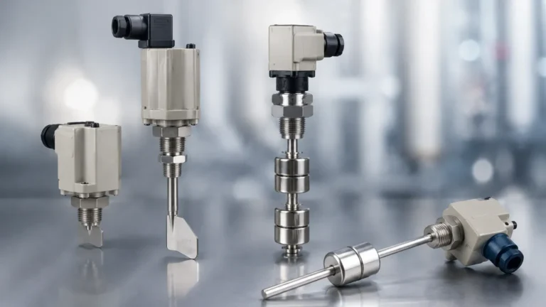
High and Low Level Switches
High and Low Level Switches
In industrial process control, point level detection serves as a critical safeguard for inventory management, equipment protection, and environmental safety. While continuous level transmitters provide a constant stream of data regarding the volume of a vessel, Level Switches act as discrete sensors that trigger an action when a specific threshold is reached. These devices are primarily categorized as high and low level switches, providing the essential "on/off" signals required to prevent overflows or dry-run conditions in pumps and boilers.
Welk, a professional manufacturer of industrial level measurement instruments, provides a diverse range of technologies designed to handle the complexities of modern automation. Understanding the underlying measurement principles and the specific requirements of high and low level applications is vital for ensuring system reliability and operational longevity.
Measurement Principles of Level Switches
Before selecting a device, engineers must understand how different technologies detect the presence or absence of a medium. Each principle offers distinct advantages depending on the physical properties of the liquid or solid being measured.
1. Float and Magnetic Principles
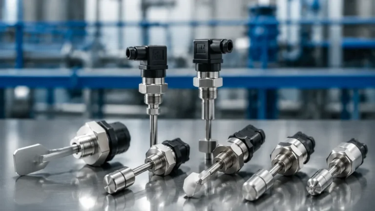
Float switches operate on the principle of buoyancy. A float containing a magnet moves with the liquid level. When the float reaches a predetermined point, the magnetic field actuates a reed switch or a microswitch located within the stem or housing. This is a purely mechanical-electrical interaction that requires no external power for the sensing element itself, making it a robust choice for simple water and oil applications.
2. Vibrating (Tuning Fork) Principle
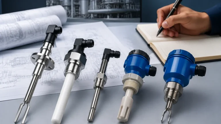
Vibrating level switches utilize a tuning fork that is piezoelectrically energized to vibrate at its natural resonance frequency in air. When the fork is immersed in a liquid or solid, the frequency shifts or the vibration is damped. An internal electronic circuit detects this change and converts it into a switching signal. This technology is highly resistant to changes in pressure, temperature, and dielectric constants.
3. Capacitive Principle
Capacitive sensors treat the probe and the tank wall (or a second probe) as two plates of a capacitor. The medium acts as the dielectric. As the level rises and covers the probe, the capacitance increases because the dielectric constant of the medium is higher than that of air. This change is measured and used to trigger the switch. These are ideal for corrosive materials but may require calibration for different media.
4. Ultrasonic and Optical Principles
Ultrasonic point level switches use a gap between two piezoelectric crystals. When liquid fills the gap, ultrasonic waves are transmitted across it; when air is present, the waves are attenuated. Optical switches use an infrared LED and a phototransistor. When liquid covers the sensor tip, the light is refracted into the liquid rather than reflected back to the transistor, signaling a level change.
The Role of High and Low Level Switches
In a standard industrial tank, high and low level switches are often installed in pairs or sets of four to provide redundancy and multi-stage control logic.
High Level Switches (Overfill Prevention)
High level switches (often designated as HL or HHL for "High-High") are installed near the top of a vessel. Their primary function is to prevent overfilling, which can lead to product loss, environmental contamination, or hazardous spills.
* Logic: Typically configured as "Normally Closed" (NC) in a fail-safe circuit, where the circuit opens if power is lost or the level is reached, immediately stopping the inlet pump or closing an intake valve.
* Applications: Chemical storage tanks, wastewater wet wells, and fuel silos.
Low Level Switches (Pump Protection)
Low level switches (LL or LLL) are positioned near the bottom of the tank. Their role is to ensure that the tank does not run dry, which is critical for protecting downstream equipment.
* Logic: These switches prevent pump cavitation by shutting down the discharge pump before the liquid level drops below the intake. They also protect immersion heaters in process tanks from burning out when exposed to air.
* Applications: Boiler feed water tanks, cooling towers, and lubricant reservoirs.
Selection Criteria for Industrial Applications
Choosing between various high and low level switches requires a detailed analysis of the process environment. The table below outlines common technologies and their suitability for different conditions.
Selection Comparison Table
| Technology | Media Type | Pressure Range | Temperature Range | Best For |
| :— | :— | :— | :— | :— |
| Float Switch | Clean Liquids | Up to 40 bar | -40°C to 150°C | Low-cost water/oil detection |
| Vibrating Fork | Liquids/Solids | Up to 64 bar | -50°C to 250°C | Viscous fluids, powders, safety loops |
| Capacitive | Liquids/Paste | Up to 25 bar | -40°C to 200°C | Corrosive chemicals, non-conductive media |
| Ultrasonic Gap | Clean Liquids | Up to 100 bar | -40°C to 150°C | High-pressure, non-contact sensing |
| Rotary Paddle | Bulk Solids | Atmospheric | -20°C to 80°C | Grain, sand, and heavy aggregates |
Material Compatibility
The wetted parts of the switch must be compatible with the process media. Welk offers materials ranging from 316L stainless steel for food and beverage applications to specialized plastics like Polypropylene (PP) or PTFE for aggressive acids. In the oil and gas sector, explosion-proof housings (ATEX/IECEx) are mandatory for high and low level switches installed in hazardous zones.
Installation and Engineering Considerations
Proper installation is as important as the technology itself. A poorly placed switch can result in false alarms or failure to trigger during a critical event.
1. Mounting Orientation:
* Side Mounting: Common for high and low level switches in large tanks. The switch is installed horizontally through the tank wall.
* Top Mounting: Preferred when the tank cannot be breached at the side or when using long-stem float switches to reach the bottom (low level) from the top flange.
2. Turbulence and Agitation: In tanks with mixers or high-velocity inflows, switches should be installed away from the turbulence or protected by a stilling well. Vibrating forks are particularly susceptible to mechanical damage if placed directly in the path of a heavy material stream.
3. Hysteresis and Deadband: Hysteresis is the difference between the point where the switch activates and where it deactivates. For high and low level switches, a controlled hysteresis prevents "chattering" (rapid cycling of pumps) when the liquid surface is wavy or turbulent.
4. Wiring and Fail-Safe Logic:
* Fail-Safe High: The switch should be energized when the level is low and de-energize when the level is high or if the power fails.
* Fail-Safe Low: The switch should be energized when the level is high and de-energize when the level drops below the set point.

Limitations and Maintenance
While Level Switches are generally low-maintenance, certain conditions can impact their performance:
* Build-up and Coating: In wastewater or slurry applications, material can build up on the sensing element. Capacitive and vibrating switches are often designed with "active shield" or frequency-shift technology to ignore coating, but mechanical floats may become stuck.
* Specific Gravity Changes: Float switches are sensitive to the density of the liquid. If the medium changes from water (SG 1.0) to a light oil (SG 0.7), the float may no longer sit at the same level relative to the surface, potentially missing the switch point.
* Pressure and Vacuum: High-pressure environments can crush hollow floats. In these cases, solid floats or non-mechanical technologies like vibrating forks or radar-based point level sensors are required.
Frequently Asked Questions (FAQs)
Q: Can I use a single switch for both high and low level detection?
A: Generally, no. A standard point level switch detects a single point. To monitor both high and low levels, you typically need two separate switches or a specialized multi-point float switch that contains two reed switches at different heights on a single stem.
Q: How do I test high and low level switches without filling the tank?
A: Many modern electronic switches, such as Welk’s vibrating forks, include a "test" button or a magnetic test point that simulates a dampening effect to verify the electronics and relay output. For mechanical floats, a manual lift rod can sometimes be used if the tank is accessible.
Q: What is the difference between a level switch and a level transmitter?
A: A level switch provides a binary output (on/off) at a specific point. A level transmitter provides a continuous signal (e.g., 4-20mA or 0-10V) representing the actual level throughout the entire height of the tank.
Q: Why is my vibrating fork switch giving false alarms in a solid silo?
A: This is often caused by "bridging" or "rat-holing," where material clings to the forks even after the bulk level has dropped. Adjusting the sensitivity or installing the switch at an angle can help shed the material.
Conclusion
High and low level switches are indispensable components in industrial safety and process efficiency. By selecting the appropriate measurement principle—whether it be the simplicity of a float or the precision of a vibrating fork—and adhering to strict installation guidelines, operators can significantly reduce the risk of equipment damage and environmental incidents. For complex applications involving high pressures, corrosive chemicals, or bulk solids, consulting with a specialized manufacturer like Welk ensures that the chosen level measurement solution meets the specific demands of the facility.